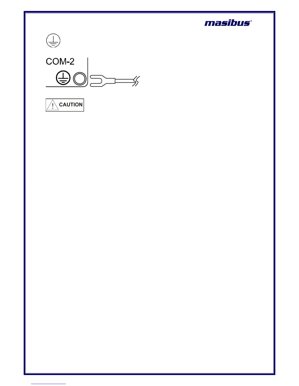
Ground the device. Otherwise, it may cause an electric shock or fire.
Connect the protective conductor terminal to earth, Use
a spade lug to make contact with the metal surface of the VMS4SE.
1 All wiring must confirm to appropriate standards of good practice and local codes and
regulations. Wiring must be suitable for Voltage, Current and temperature rating of the system.
2 Provide power from a single-phase instrument power supply. If there is a lot of noise in the
power line, insert an insulating transformer into the primary side of the line and use a line filter
on the secondary side. Do not place the primary and secondary power cables close to each
other.
3 High voltage transients may occur when switching inductive loads such as some contactors.
Through the internal contacts, these transients may introduce disturbances which could affect
the performance of the instrument.
4 For this type of load it is highly recommended that a “snubber” is connected across the normally
open contact of the relay switching through load. The recommended snubber consists of a
series connected resistor/capacitor (typically 15nF/100Ohms). In addition a snubber will prolong
the life of the relay contacts. A snubber should also be connected across a trick output to
prevent false triggering under line transient conditions.
 Loading...