MDS 05-2806A01, Rev. A MDS iNET 900 User’s Guide 109
6.1 DATA INTERFACE CONNECTORS
Three data interface connectors are provided on the face of the
iNET 900. The first, the LAN Port, is an RJ-45 connector. The other two
use two DB-9 interface connectors that use the RS-232 (EIA-232) sig-
naling standard. Note that the connector for
COM1 Port is DCE (Female
DB-9) and the
COM2 Port is DTE (male DB-9).
The iNET 900 unit meets U.S.A.’s FCC Part 15, Class A limits when
used with shielded data cables.
6.1.1 LAN Port
The LAN Port is used to connect the radio to an Ethernet network. The
iNET unit will provide a data link to an Internet Protocol-based (IP) data
network through the radio network’s Access Point station. Each
iNET 900 in the network must have a unique IP address for the network
to function properly.
To connect a PC directly to the radio’s
LAN port, an RJ-45 to RJ-45
straight-through cable is required. The connector uses the standard
Ethernet RJ-45 cables and wiring. For custom-made cables, use the
pinout information below.
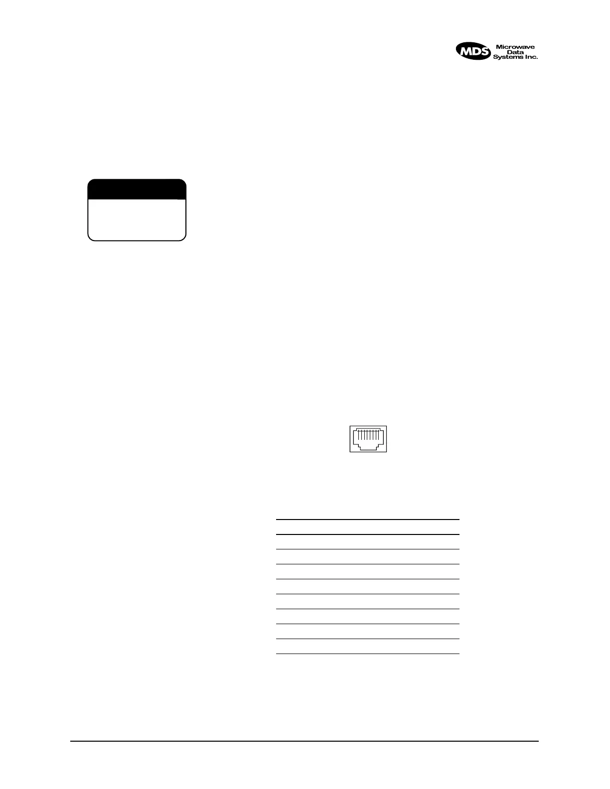
Figure 6-1. LAN Port (RJ-45) Pinout
(Viewed from the outside of the unit)
Table 0-1. LAN Port (IP/Ethernet)
Pin Functions Ref.
1 Transmit Data (TX) High
2 Transmit Data (TX) Low
3 Receive Data (RX) High
4 Unused
5 Unused
6 Receive Data (RX) Low
7 Unused
8 Unused
CAUTION
RADIO FREQUENCY
INTERFERENCE
POTENTIAL
1 2 3 4 5 6 7 8