MDS 05-2806A01, Rev. A MDS iNET 900 User’s Guide 79
3.1 OVERVIEW
It is convenient to set up a tabletop network that can be used to verify
the basic operation of the MDS iNET 900 units and give you a chance
to experiment with network designs, configurations or network equip-
ment in a convenient location. This test can be performed with any
number of MDS iNET 900 radios.
One of the MDS iNET 900 units in this mini-network must be set to
Access Point service (Device Mode = Access Point) for proper opera-
tion.
NOTE: It is important to use a “Network Name” that is different from
any currently in use in your area during the testing period. This
will eliminate unnecessary disruption of traffic on the existing
network while you become familiar with the MDS iNET 900
or evaluate variations of unit operating parameters.
To simulate data traffic over the radio network, connect a PC or LAN to
the Ethernet port of the Access Point and PING each iNET 900 several
times.
3.2 STEP 1—INSTALL THE ANTENNA
CABLING
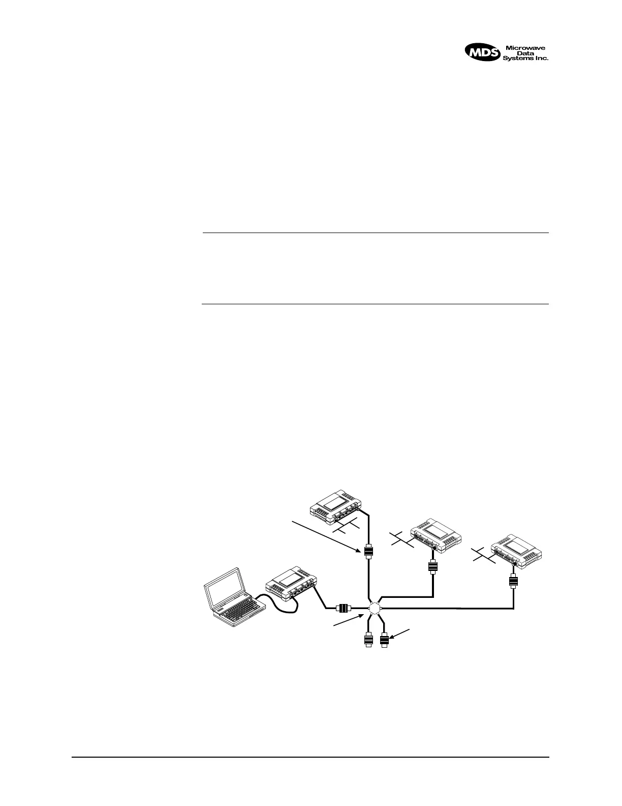
Figure 3-1 is a drawing of the tabletop arrangement. Connect the
antenna ports of each iNET 900 as shown. This will provide stable radio
communications between each unit while preventing interference to
nearby electronic equipment from a large number of collocated units.
Invisible place holder
Figure 3-1. Typical setup for tabletop-testing of radios
POWER ATTENUATORS
• Fixed or adjustable
• 1W Minimum Rating
POWER DIVIDER
NON-RADIATING ATTENUATORS
• Install on unused divider ports (if any)
• 1W Minimum Rating
COMPUTER
L
A
N
C
O
M
1
C
O
M
2
P
W
R
L
I
N
K
L
A
N
C
O
M
1
C
O
M
2
P
W
R
L
IN
K
iNET 900
Remote
iNET 900
Remote
iNET 900
Access Point
iNET 900
Remote