MDS 05-2806A01, Rev. A MDS iNET 900 User’s Guide 83
Invisible place holder
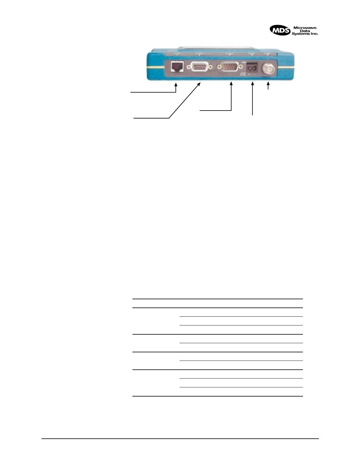
Figure 3-3. MDS iNET Interface Default Configuration & Functions
3.7 STEP 6—CHECK FOR NORMAL
OPERATION
Once the data equipment is connected, you are ready to check the
iNET 900 for normal operation.
Observe the iNET LEDs on the top cover for the proper indications. In
a normally operating system, the following LED indications will be seen
within 30 seconds of start-up:
•
PWR—Lit continuously
• LINK—on or blinking intermittently
• LAN—On or blinks intermittently
Table 3-2 provides details on the LED functions.
Table 3-2. MDS iNET 900 LED Functions
LED Label Activity Indication
LAN ON LAN detected
Blinking Data TX/RX
OFF LAN not detected
COM1
(MGT System)
Blinking Data TX/RX
OFF No data activity
COM2 Blinking Data TX/RX
OFF No data activity
PWR ON Primary power (DC) present
Blinking Alarm present
OFF Primary power (DC) absent
COM2
◆ DTE Serial Data Equip.
◆ 9,600 bps/8N1
◆ Full Handshaking
◆ RS/EIA-232.
LAN
◆ 10BaseT
◆ IP/Ethernet Port
◆ IP Address: 192.168.1.1
COM1
◆ DCE Console/Terminal
◆ 19,200 bps/8N1
◆ No Handshaking
◆ RS/EIA-232
PRIMARY POWER
◆ 13.8 Vdc @ 500 ma
(10.5–30 Vdc)
◆ Negative Ground
◆ + Left – Right
ANTENNA
◆ 50Ω TNC
◆ +30 dBm/1W Out (Max.)
◆ –30 dBm Input (Max.)