“4069RT” Service and Parts ManualMarch 2014
Page 4-6
TROUBLESHOOTING -- ELECTRICAL SYSTEM TROUBLESHOOTING
M
ATRIX
M
ODULE
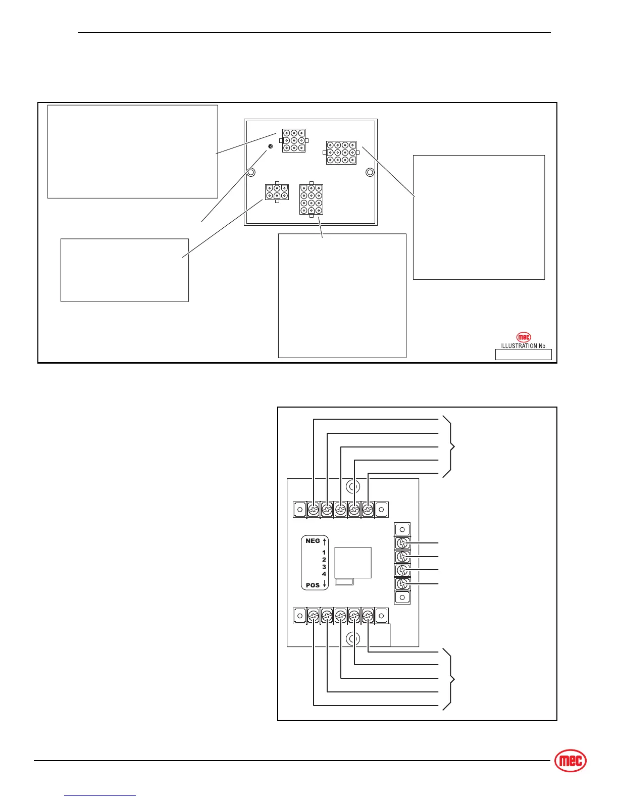
The Matrix Module is the remote module located inside the upper control box. It
received inputs from the operator and relays them to the GP400.
Figure 4a-2: Matrix Module
T
ERMINAL
B
LOCK
M
ODULE
(TBM)
Figure 4a-3: Terminal Block Module (TBM)
There is a module inside the
lower control box, called a TBM
(Terminal Block Module) that
provides terminal point
connections for both positive and
ground circuits. A signal from the
Emergency Stop circuit activates
a load-reduction relay within the
TBM that provides ample power
to the B+ (positive) terminal strip.
This arrangement protects the
system against voltage drop
conditions that can be
detrimental to the electrical
system.
ART_3159
Matrix Module (inside Upper Control Box)
1
10
3
13
46
12
1
10
3
12
1
7
3
9
Diagnostic
LED
P4-1 — not used
P4-2 — not used
P4-3 — not used
P4-4 — Level Indicator Lamp
P4-5 — Alarm
P4-6 — DriveEnabled Lamp (Outriggers Option)
P4-7 — not used
P4-8 — not used
P4-9 — not used
P3-1 — High Speed
P3-2 — Switch Supply
P3-3 — not used
P3-4 — DRIVE
P3-5 — LIFT
P3-6 — NOT USED
P3-7 — not used
P3-8 — not used
P3-9 — not used
P3-10 — UP Switch
P3-11 — DOWN Switch
P3-12 — not used
P1-1 — 12 Volts DC INPUT: Power-up
P1-2 — not used
P1-3 — CAN BUS H
P1-4 — Ground
P1-5 — not used
P1-6 — CAN BUS L
P2-1 — FORWARD / DOWN
P2-2 — REVERSE / UP
P2-3 — STEER Left
P2-4 — STEER Right
P2-5 — Enable Bar
P2-6 — Potentiometer
P2-7 — not used
P2-8 — not used
P2-9 — not used
P2-10 — Potentiometer
P2-11 — Potentiometer
P2-12 — Switch Supply
GROUND
(B−) Connection
PLATFORM Selected
BASE Selected
ANALOG (AMP)
COMMON B+
POSITIVE OUTPUT
(B+) Supply
To various circuits
ART_3186