“4069RT” Service and Parts Manual March 2014
Page 3-11
DRIVE MOTORS
D
RIVE
M
OTORS
NOTE: Refer to Section 1 for seal replacement instructions.
Refer to Parts Section D and E for detailed parts list and illustration.
There are four hydraulic drive motors on this machine. Repair or replace as necessary
when damage or leaks occur.
• Clean all fittings before disconnecting hoses.
• Tag hoses for proper reassembly.
• Plug all openings immediately to prevent contamination.
Refer to “Lift and Support The Machine” in the Introduction section for instructions and
safety precautions.
R
EAR
D
RIVE
M
OTORS
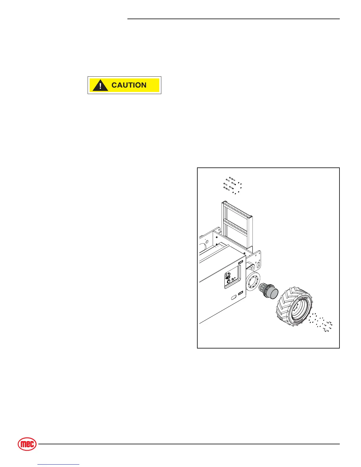
Figure 3-6: Rear Drive Motor
Removal
1. Raise and support the rear end of
machine.
2. Raise the scissor arm assembly and
support using the maintenance lock.
3. Remove the wheel and tire assembly.
4. Disconnect hydraulic hoses. Immedi-
ately cap and plug all openings to pre-
vent contamination.
5. Remove the bolts that attach the
motor to the chassis.
Installation
Installation is reverse of removal.
• Use Loctite
242 or equivalent on mount-
ing bolts.
• Torque all bolts to 55 lb-ft (75Nm).
ART_4497