“4069RT” Service and Parts ManualMarch 2014
Page 2-14
CONTINUITY CHECKS
C
ONTINUITY
C
HECKS
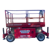
Figure 2-11: Selector Switch
S
ELECTOR
S
WITCH
– ON-OFF
• Disconnect wires.
• Connect first probe of ohm meter to common terminal.
• Connect second probe to any normally open terminal.
• With switch OFF (open) there should be no reading.
• With the switch ON (closed) there should be a low
reading.
• Repeat for each normally open terminal.
T
OGGLE
S
WITCH
– ON-OFF
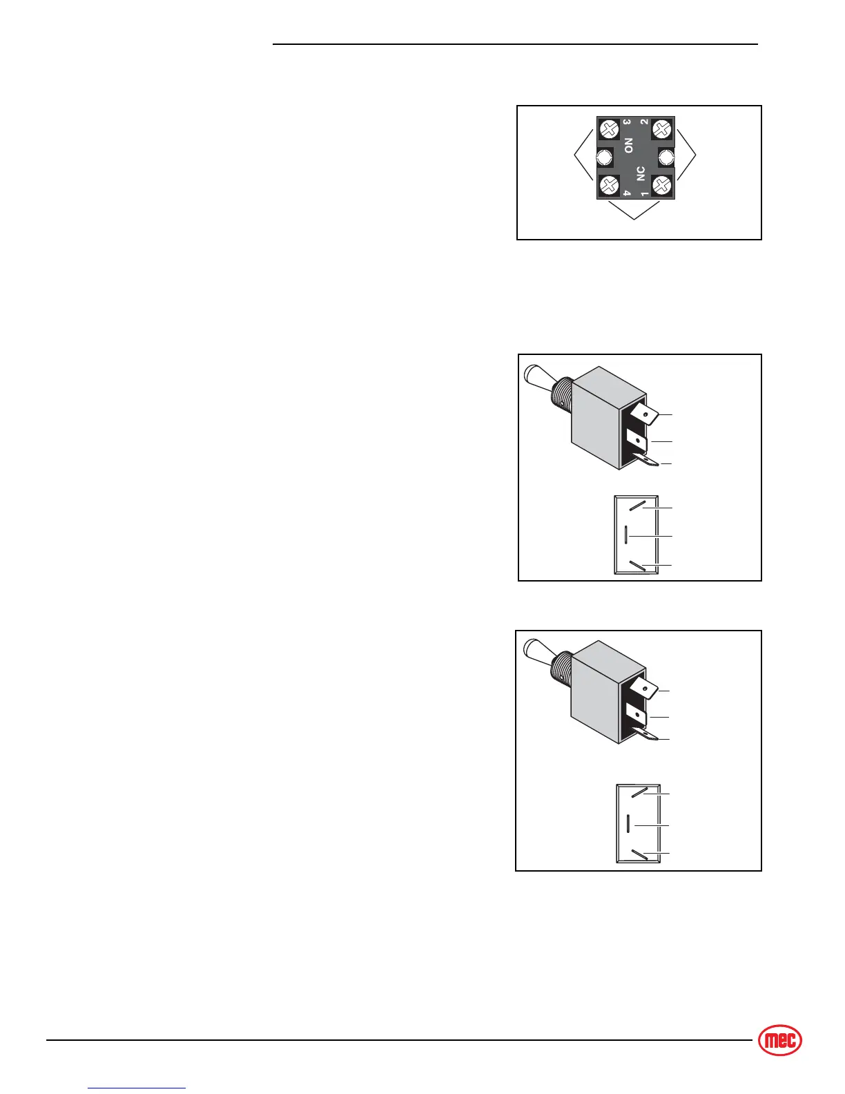
Figure 2-12: Toggle Switch, ON-OFF
• Disconnect wires.
• Connect first probe of ohm meter to common terminal.
• Connect second probe to normally open terminal.
• With the switch turned OFF there should be no reading.
• With the switch turned ON there should be a low resis-
tance.
T
OGGLE
S
WITCH
– 1-P
OLE
2-P
OSITION
Figure 2-13: Toggle Switch, 1-Pole 2-Position
• Disconnect wires.
• Connect first probe of ohm meter to common termi-
nal.
• Connect second probe to top normally open terminal.
• With toggle DOWN there should be no reading.
• With the toggle UP there should be a low resistance.
• Move second probe to bottom normally open terminal.
• With toggle UP there should be no reading.
• With the toggle DOWN there should be a low resis-
tance.
Common
Normally
Open
Normally
Closed
ART_3153
Common
Normally Open
Not Used
Common
Normally Open
Not Used
ART_2562
Common
Normally Open
Normally Open
Common
Normally Open
Normally Open
ART_2563