“4069RT” Service and Parts ManualMarch 2014
Page 2-16
CONTINUITY CHECKS
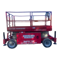
Figure 2-16: Button Switch, Momentary
M
OMENTARY
B
UTTON
S
WITCH
• Disconnect wires.
• Connect one probe of ohm meter each terminal.
• With the button in the neutral (open) position there
should be no reading.
• With the button pushed (closed) there should be a low
resistance
Figure 2-17: Emergency Stop Switch
E
MERGENCY
S
TOP
B
UTTON
• Disconnect wires.
• Connect one probe of ohm meter each terminal.
• With the button PRESSED there should be no reading.
• With the button RESET there should be a low resistance.
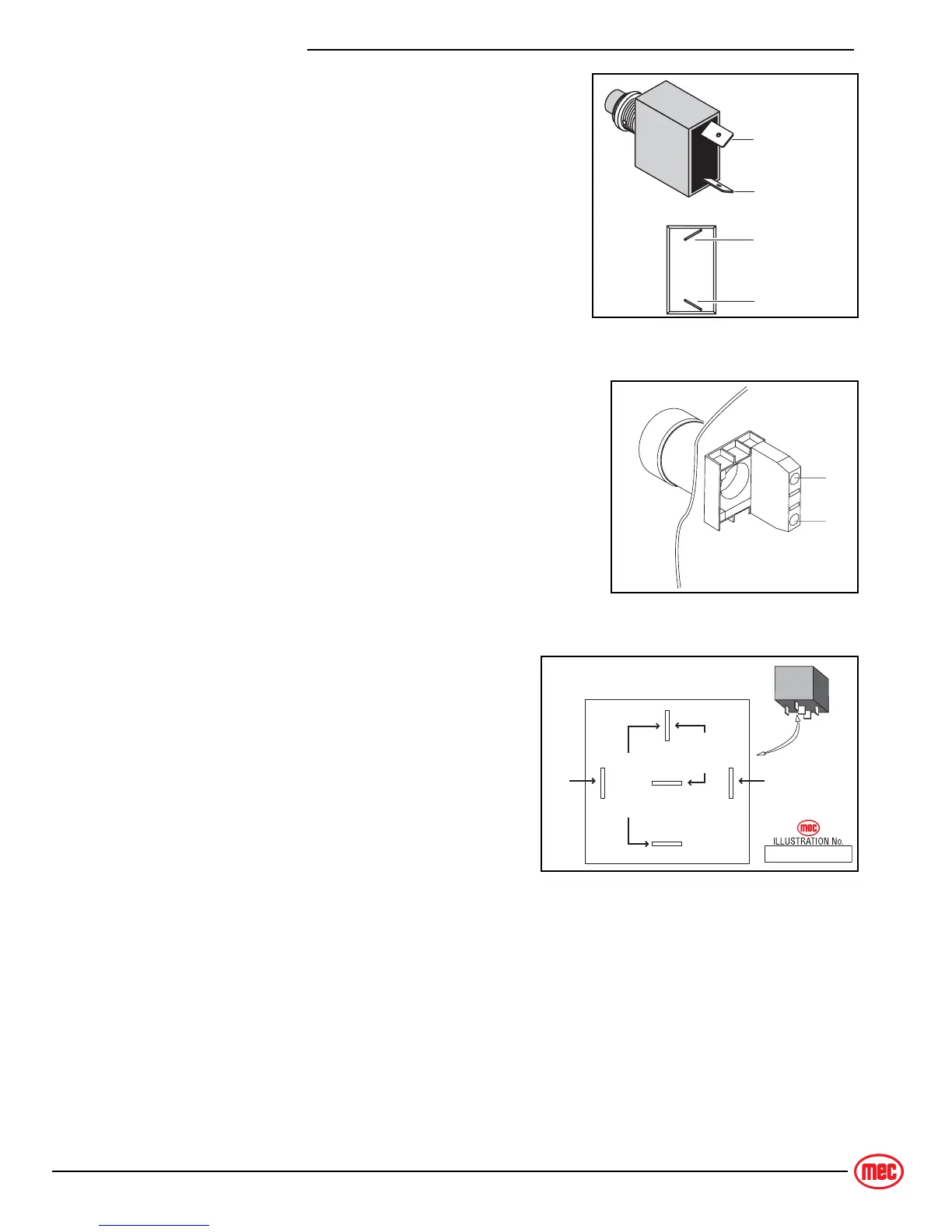
Figure 2-18: Relay Operation
R
ELAY
• With the #85 terminal grounded, apply voltage to
#86 terminal connection.
• Confirm normally closed (#87A) contacts are
opening. Continuity with #30 will be broken.
• Confirm normally open (#87) contacts are clos-
ing. Continuity with #30 will be made.
Common
Normally Open
Common
Normally Open
ART_2565
1
1A
ART_2566
ART_2330
RELAY DETAIL
(relay energized)
85 86
87
87A
30
OPEN
CLOSED
B+B−