6.3 Diode test
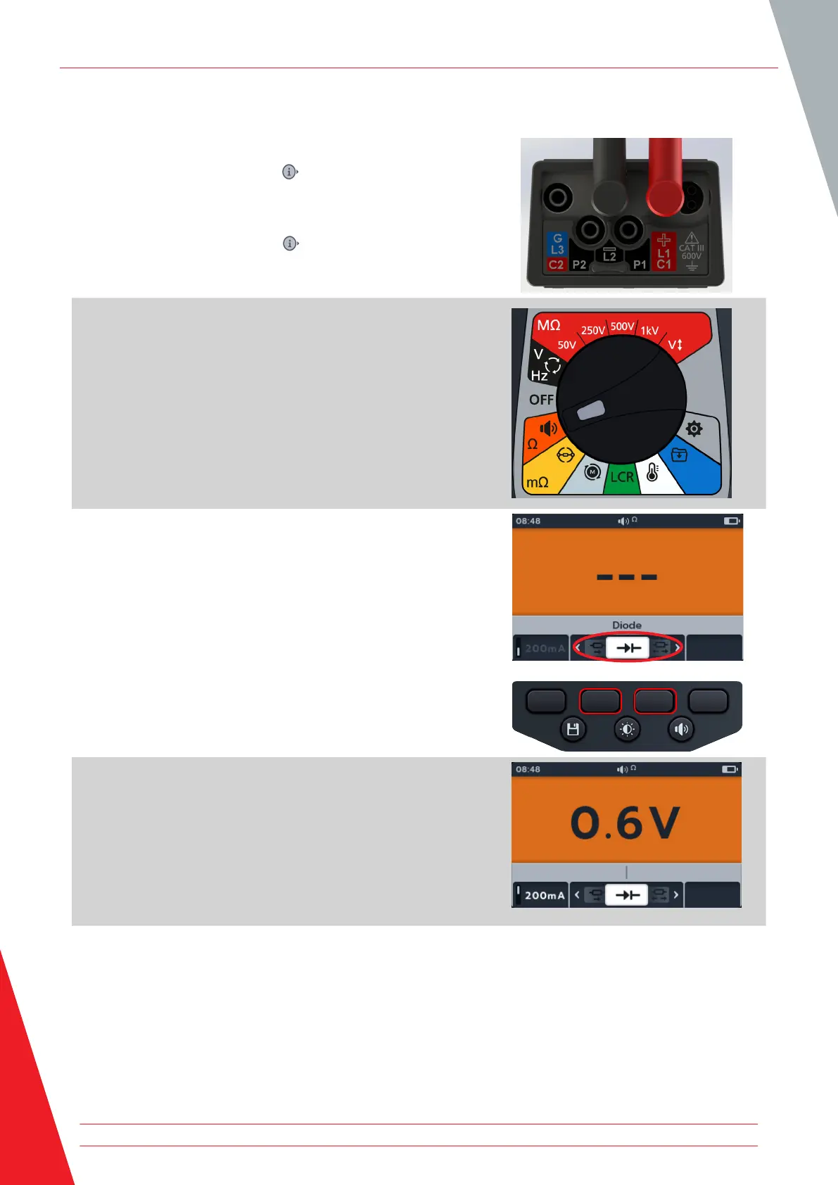
1. Connect the test leads to the MTR105.
1.1. Press the Information ( ) button to view the lead set
up diagram.
NOTE: When the diagram is displayed a test cannot be
performed. Press Information ( ) button to return to the test
screen.
2. Turn rotary switch to select Continuity position.
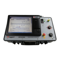
3. Press soft keys 2 and 3 to move the carousel left or right
through sub-modes to Diode test.
NOTE: The full title text of the sub-mode will appear in the
secondary field for a few seconds.
4. This test starts automatically.
5. During the tests, the primary field displays the voltage drop
as it is measured.
A good forward-biased diode displays a voltage drop ranging from 0.5 to 0.8 V for the most commonly used
silicon diodes. Some germanium diodes have a voltage drop ranging from 0.2 to 0.3 V. The voltage drop is also
dependent on the test current.
The meter displays O/C when a good diode is reverse-biased. The O/C reading indicates the diode is functioning
as an open switch.
A bad (open circuit) diode does not allow current to flow in either direction. The meter will display O/C in both
directions when the diode is opened.
A short circuited diode has zero voltage drop reading in both directions.
Continuity
36 www.megger.com