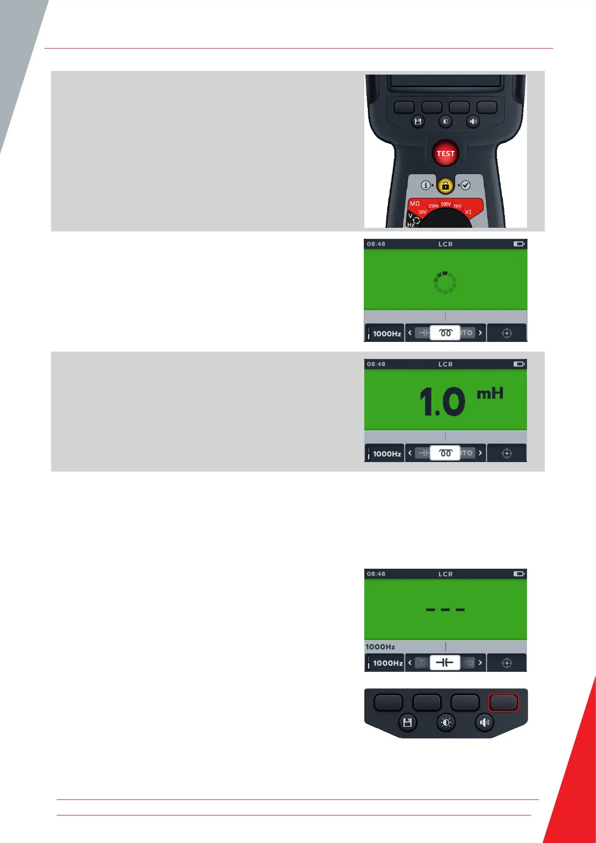
6. To start the test press the TEST button.
The MTR105 determines if the load is inductive, capacitive or
resistive automatically.
7. During the tests,
The primary field displays a rotating circle to show a test
is underway.
The secondary field displays the frequency.
8. During the tests,
The primary field displays the result for the reactive
component. (This could be capacitance, inductance or
resistance).
The secondary field displays the frequency.
9.3 LCR Calibration
NOTE For full MTR105 re-calibration procedure refer to Refer to 18. Calibration, Repair and Warranty on page 84.
1. Inductance calibration can be accessed from any sub-mode
within the LCR family by pressing soft key 4.
Inductance (L); Capacitance (C); Resistance (R) (LCR)
www.megger.com 51