Description 6.2 Liter (377 cid)
Margin after surfacing Intake 0.79 mm (0.0311 in.) minimum
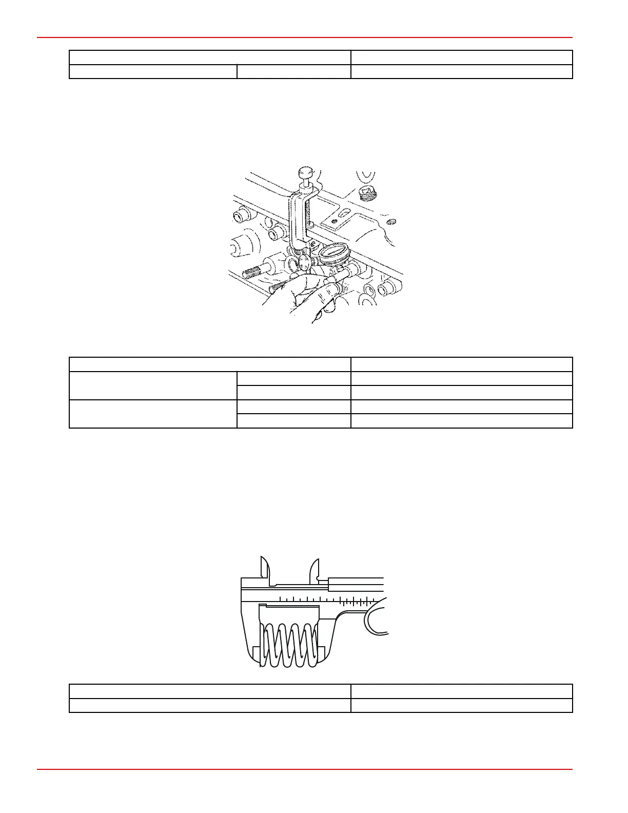
Valve Stem to Bore Clearance
1. Using a valve with a specified stem diameter or a new valve, measure valve stem clearance.
2. Attach a dial indicator to the cylinder head. Position it against the valve stem and close to the valve guide.
3. Holding the valve head off the seat about 0.158 cm (1/16 in.), move the valve stem side to side in the guide as shown.
Compare the stem clearance with the specifications.
Measuring stem clearance
Description 6.2 Liter (377 cid)
Production
Intake 0.023–0.065 mm (0.0009–0.0025 in.)
Exhaust 0.033–0.075 mm (0.0012–0.00295 in.)
Service
Intake 0.025–0.094 mm (0.0010–0.0037 in.)
Exhaust 0.025–0.094 mm (0.0010–0.0037 in.)
4. If the clearance exceeds specifications on the exhaust valve and exhaust guide: it is necessary to replace the cylinder
head or install thin wall valve guide inserts.
5. If the clearance exceeds specifications on the intake valve and intake guide: it is necessary to install thin wall valve guide
inserts (Goodson, K‑Line) or replace the cylinder head. Intake valves are not available with oversize stems.
NOTE: The only engine machine shop reconditioning of the valve guides should be done with thin wall valve guide inserts
(Goodson, K‑Line, etc).
Valve Springs
1. Use a vernier caliper to measure the valve spring free length. This is for reference only, springs should be measured for
load at specified heights to determine if they are good.
Description 6.2 Liter (377 cid)
Free length 53.39 mm (2.10 in.)
Engine Inspection and Assembly
Page 3B-46 © 2016 Mercury Marine 90-8M0099748 eng DECEMBER 2015

 Loading...


