Table of figures
■■■■■■■■■■■■■■■■■■■■■■
VI
■■■■■■■■
876 Dosimat plus
Table of figures
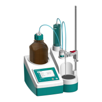
Figure 1 Front 876 Dosimat plus ..................................................................... 6
Figure 2 Rear 876 Dosimat plus ...................................................................... 7
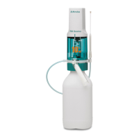
Figure 3 Manual Dosing Controller 6.2107.100 ............................................... 8
Figure 4 Connecting a stirrer ........................................................................... 9
Figure 5 Connecting the Manual Dosing Controller ....................................... 10
Figure 6 Connecting a balance ...................................................................... 10
Figure 7 Connecting USB devices .................................................................. 11
Figure 8 Connecting the USB stick ................................................................ 12
Figure 9 Connecting the 6.2147.000 USB keyboard with USB stick and
printer ............................................................................................. 13
Figure 10 Connecting the USB hub with USB stick, printer and the 6.2148.030
RS-232/USB Box (for connecting balances). ...................................... 13
Figure 11 Connecting a remote cable .............................................................. 13
Figure 12 Connecting the 805 Dosimat ........................................................... 14
Figure 13 MSB connector on the 801 Stirrer ................................................... 14
Figure 14 Attaching the exchange unit ............................................................ 15
Figure 15 Keypad 876 Dosimat plus ................................................................ 18
Figure 16 Directory structure on the USB flash drive ........................................ 36
Figure 17 Dosing ramp, two examples ............................................................ 43
Figure 18 Tandem operation ........................................................................... 49
Figure 19 Rotational speed depending on the stirring rate ............................... 54
Figure 20 Pin assignment of remote socket and remote plug ........................... 58
Figure 21 Remote status diagram DOS ............................................................ 59
Figure 22 Remote status diagram DOS with pulse control ............................... 60
Figure 23 Remote status diagram XDOS .......................................................... 60
Figure 24 Connecting the RS-232/USB Box to the PC ...................................... 62