EasyManuals Logo

Microtest 6632 Series User Manual

Default Icon
106 pages
To Next Page IconTo Next Page
To Previous Page IconTo Previous Page
Page #18 background imageLoading...
Page #18 background image
13
Handler I/O timing diagram
NOTE:
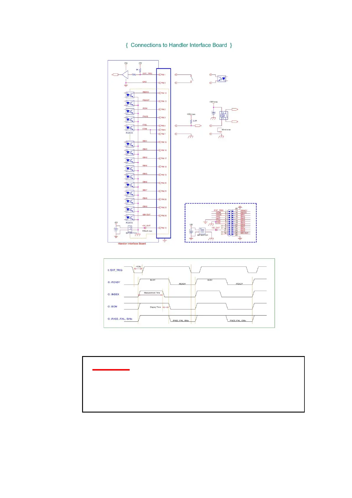
1. PIN1(trigger) + PIN5(gnd) Start testing after short circuit,
the shorting time must be greater than 100uS.
2. The other output pins are photo coupler circuit, output
signal is low level.The output is as a high resistance
floating circuit when it without action.
3. /EOM and /INDEX will be clean after the /TRIGGER
executed.

Table of Contents

Questions and Answers:

Question and Answer IconNeed help?

Do you have a question about the Microtest 6632 Series and is the answer not in the manual?

Microtest 6632 Series Specifications

General IconGeneral
BrandMicrotest
Model6632 Series
CategoryMeasuring Instruments
LanguageEnglish

Related product manuals