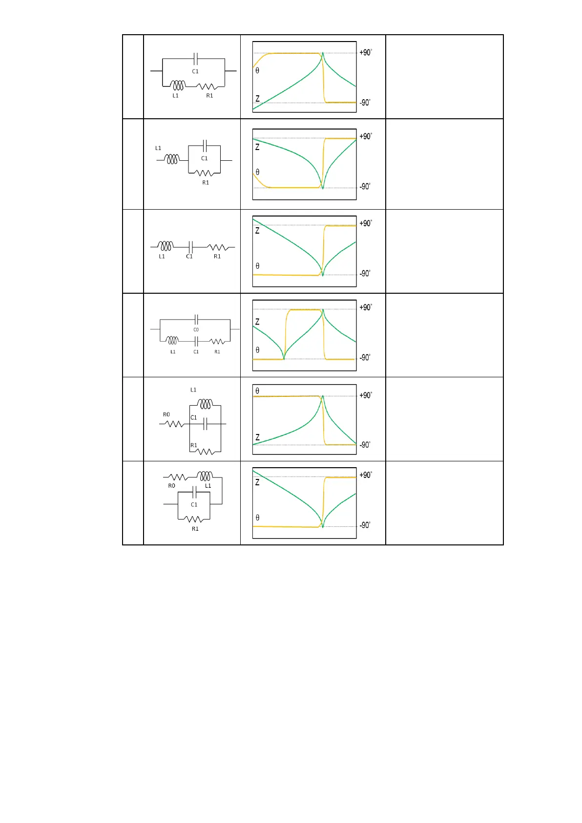
Home
Microtest
Measuring Instruments
6632 Series
Microtest 6632 Series User Manual
4
of 1
of 1 rating
106 pages
Give review
Manual
Specs
To Next Page
To Next Page
To Previous Page
To Previous Page
Loading...
46
B
Inductor:
Inductor with
comparatively high ESR
Resistor: Resistor
with
low resistance value
and significant wiring
inductance eff
ect
C
Capacitor: Capaci
tor
with significant leak
resistance eff
ect
Resistor: Resistor
with
high resistance value
and significant stra
y
capacitance
eff
ect
D
Capacitor:T
ypicalcapaci
tor
E
Piezoelectric elem
ent
Resonator
F
Inductor with high E
SR
G
Capacitor with high E
SR
*Typical frequency
characteristics gra
phs
For
models
A,
B,
C,
D,
F
and
G,
the
horizontal
axis
is
logarithmic,
the
vertical
axis (Z) is lo
garithmic, and
θ
is linear
.
For
model
E,
the
horiz
ontal
axis
is
linear
or
logarithmic,
the
vertical
axis
(Z)
is
logarithmic and
θ
is
linear.
50
52
Table of Contents
Default Chapter
3
Table of Contents
3
1 Safety Specification
7
2 Preface
9
Introduction
9
Key Feature
9
Specification
10
3 Description of Installation
12
Package & Equipment
12
Description of Function Keys on Front Panel
13
Description of Function Keys on Back Panel
14
Hardware Installation
15
GPIB Connecting
15
RS232 Connecting
16
Handler Interface
17
Fixture Connecting
19
LAN Port
20
Power Cord Connecting
21
4 Basic Measuring
22
Meter Mode
22
Freq(Frequency)
22
Level
22
Range Ac
22
Speed
22
Bias
23
Range DC
23
Trig
23
Comp
23
Parameters
24
Measurer Mode Setup
25
Trigger Delay
25
Ac/DC Delay
25
Average
25
DISPLAY VM/IM
25
Beep When
26
Statistics
26
Font Size
26
Trigger Mode
27
Level/Ro/Alc
27
Output Impedance)
27
ALC (Auto Level Control)
28
SET Ε
29
Dielectric Coefficient Measurement Method
29
SET Μ
30
Magnetic Permeability Coefficient Measurement Method
30
COMP (Comparison)
31
Comparator Setup
31
COMP (Comparator) MODE & DISP (Display) Mode
32
Upper
33
Lower
33
Bin Setup
33
PARAMETER and bin NUMBER
33
Bin Method
34
File
36
Recal
36
New
36
Save as
36
Delete
36
Usb File
37
Copy>Usb
37
5 List Test
38
List Set
38
List Mode Setup
39
Trigger Mode
39
Trigger Delay
39
Automatic Trigger Determination Point Mode
39
Output Impedance
40
Alc
40
Beep When
40
Range Hold
40
Fail Retset
40
Statistics
41
Terminated at Ng Step
41
Preset
41
Corr.(List Correction)
41
6 Sweep
42
Sweep Mode Setup
42
Sweep Delay
43
Output Impedance
43
Keep Previous Trace
44
Trace A/B Color
44
Preset
44
Cursor
45
Auto Fit
45
Type
45
X-Axis
46
Start/Stop
46
Level
46
Trig
46
Speed
47
Func
47
Trace A/B para
47
Trace A/B Y-Axis
48
Trace A/B Ref
48
Trace A/B Pos
48
Trace A/B DIV/Decade
49
Equivalent Circuit Analysis (Option)
50
7 Correction
52
Open Circuit Correction
53
Short Circuit Correction
54
Hf Load
55
Spot Load
55
Cable Length
55
Fixture Compensation
56
Spot. no
56
Frequenncy
56
Load Function
57
Reference
57
Load
57
8 System Cnofig
58
Language
58
Gpib Address
58
Rs232 Baud Rate
58
Rs232 Eoi
58
Lan Port
59
Handlerinterface
60
Key Beep
60
Appendix
61
Z| Accuracy Chart
61
Measurement Accuracy
62
Concept of Command
64
Subsystem Command Tree
64
Data Format
65
Common Commands
66
Measure Subsystem
70
LIST Subsystem
78
Sweep Subsystem
85
Read the Measured Value
93
Measurement Basics
94
Resistance (R) and Conductance (G)
95
Capacitance (C)
96
Inductance (L)
97
Reactance (X) and Susceptance (B)
98
Impedance (Z) and Admittance (Y)
99
Quality Factor (Q) and Dissipation Factor (D)
100
Phase Angle (Θ)
101
Overall Impedance Measurement Theory
102
Characteristics Example
105
High and Low Impedance Criteria
106
4
Based on 1 rating
Ask a question
Give review
Questions and Answers:
Need help?
Do you have a question about the Microtest 6632 Series and is the answer not in the manual?
Ask a question
Microtest 6632 Series Specifications
General
Brand
Microtest
Model
6632 Series
Category
Measuring Instruments
Language
English
Related product manuals
Microtest 6375
95 pages
Microtest 6377
95 pages
Microtest 6378
95 pages