13
Upon completing this step, please insert the
detachable terminal block into the meter control
power supply connector housing.
An isolation transformer or EMC lter may need
to be installed before feeding into the power
meter in case of power quality problems in the
control power supply.
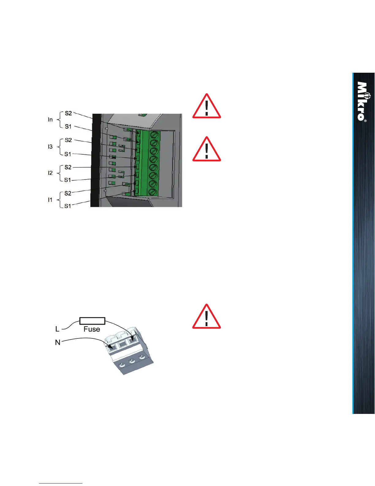
e) remove the detachable terminal block from the
meter control power supply connection and
connect the control power supply via a fuse
to the terminal block as shown in Fig 11. The
recommended wire size is AWG 16 ~ 20.
The recommended fuse part no is LVSP5 from
Littelfuse. Please note that without this fuse, the
meter installation is only rated at CAT II. For CAT
II installations, an adequate circuit breaker or fuse
according to local regulations should be installed.
Please make sure the power to the
meter control is totally removed.
The meter control power supply
MUST be connected via an external
circuit breaker and be protected by a
CAT IV fuse.
Fig 10 :
3-phase and neutral CT connections
Fig 11 :
Control power connections
Installation 2.2
The terminal block must be inserted
securely into the connector housing
on the meter to prevent improper
operation.
Installation 2.2