9
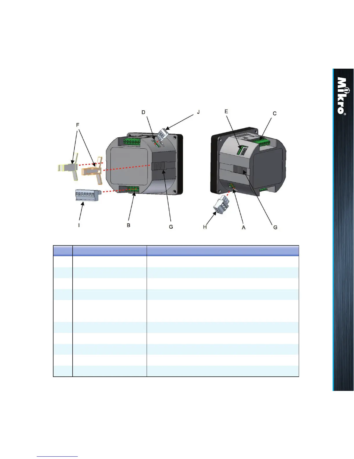
The parts and locations in the meter where connections and
fastening are made is shown in Fig 3 and Table 2:
Fig 3 : Parts location
Table 2 : Location and parts labels
Label
A
B
C
D
E
F
G
H
I
J
Part / Location Description
Control power input Meter control power supply
Voltage input Metering voltage connection
Current input Metering current connection
RS-485 port RS-485 connection for Modbus RTU
RJ45 port LAN connection for Modbus TCP/IP & webserver
(only for DPM680)
Retainer clip
Retainer clip slot
Control power plug
RS-485 plug
Voltage input plug
Clip to hold meter in cut out hole
Location to slide the retainer clips
Meter control power detachable terminal block
RS-485 detachable terminal block
Metering voltage detachable terminal block
Introduction 1.3