46
Pellerin Milnor Corporation
You must make sure that the reservoir has fluid to prevent air flow into the system from
the reservoir
b. Apply electrical power to the machine. Release the brake.
c. See the part of the machine reference manual that tells how to operate the outputs
manually.
d. Put a small quantity of new brake fluid (approximately inches (50 mm)) in the 12 ounce
container (Figure 21 , item 1).
e. Do these steps for each bleed valve (Figure 18 , item 1) . Two technicians are necessary.
This will move the fluid in one direction and push air out of the line:
• Attach a clean tube to the valve. Put the other end in the container (Figure 21 , item 1)
below the fluid.
• Make sure that the reservoir is full of fluid.
• Apply the brake (See Section : Operation of Brake Systems, page 48).
• Open the bleed valve. (Figure 19 , item 12)
• Look for air bubbles in the container when you push the air and fluid out through the
tube.
• Close the valve.
• Release the brake.
• Continue the steps above until no more air comes out of the line.
f. Add fluid to the top of the reservoir. Replace the cap.
g. Operate the brake many times. Make sure that it operates correctly.
How to Adjust the Connection between the Brake Cylinder
and the Air Cylinder
BNWUUM03.T05 0000277686 A.4 A.7 3/17/20 2:24 PM Released
If you removed the brake cylinder or the air cylinder, you must adjust this connection.
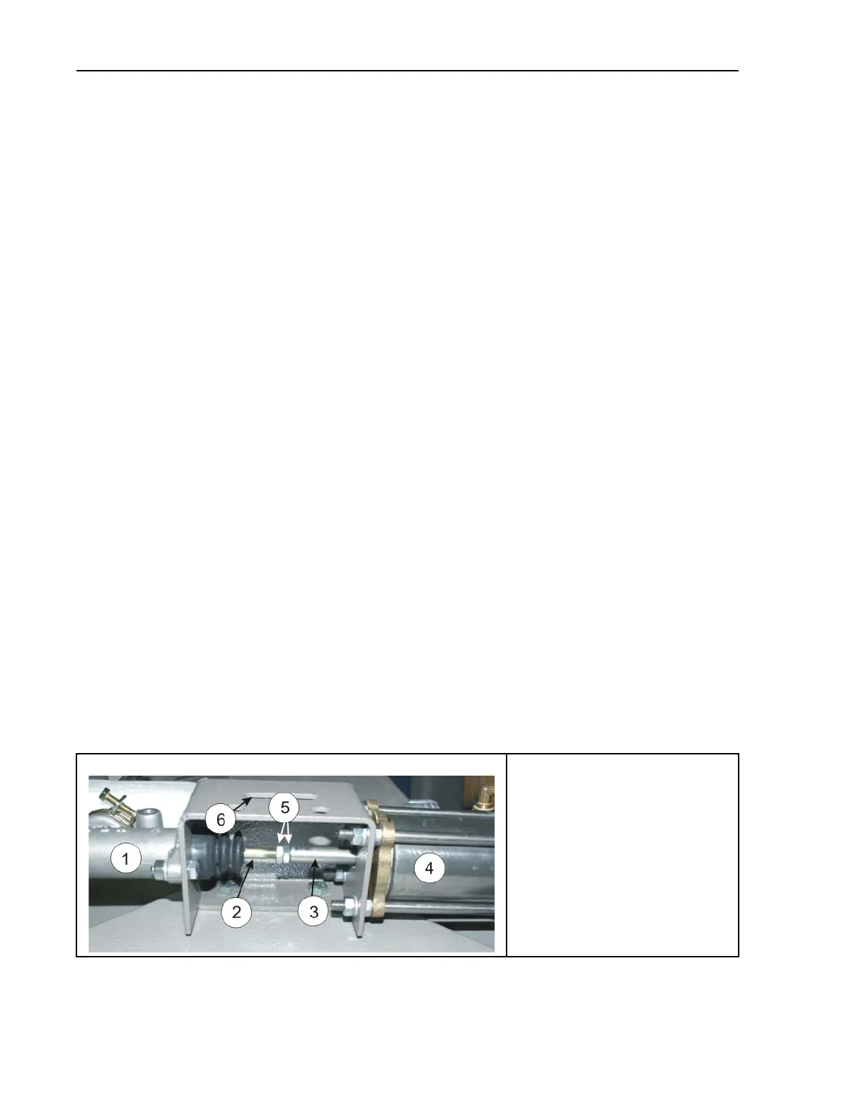
Figure 22. The Connection between the Brake Cylinder and the Air Cylinder
A view of the brake rod and related components
Legend
1. The brake cylinder
2. The rod for the brake cylinder
3. The rod for the air cylinder
4. The air cylinder
5. Two nuts to lock the rods together
6. The slot to see the nuts
Drive Assemblies