Pellerin Milnor Corporation 73
These measurements are taken in thousandths of an inch. Although this requires precise work,
attention to detail and a good set of feeler gauges, it is the only way to insure that the bearing
will be tightened onto the shaft to precisely the right tension. If you have any questions on
performing the measurements or adjustments described below, your local bearing supplier or
the Milnor
®
factory can assist you. Although these procedures require precision over and
above that normally required for laundry room maintenance, they are standard in bearing in-
stallation and absolutely essential:
NOTE: Step 4 requires a good set of feeler gauges including .001" through .010" in
thousandths of an inch increments. Contact your local bearing supplier.
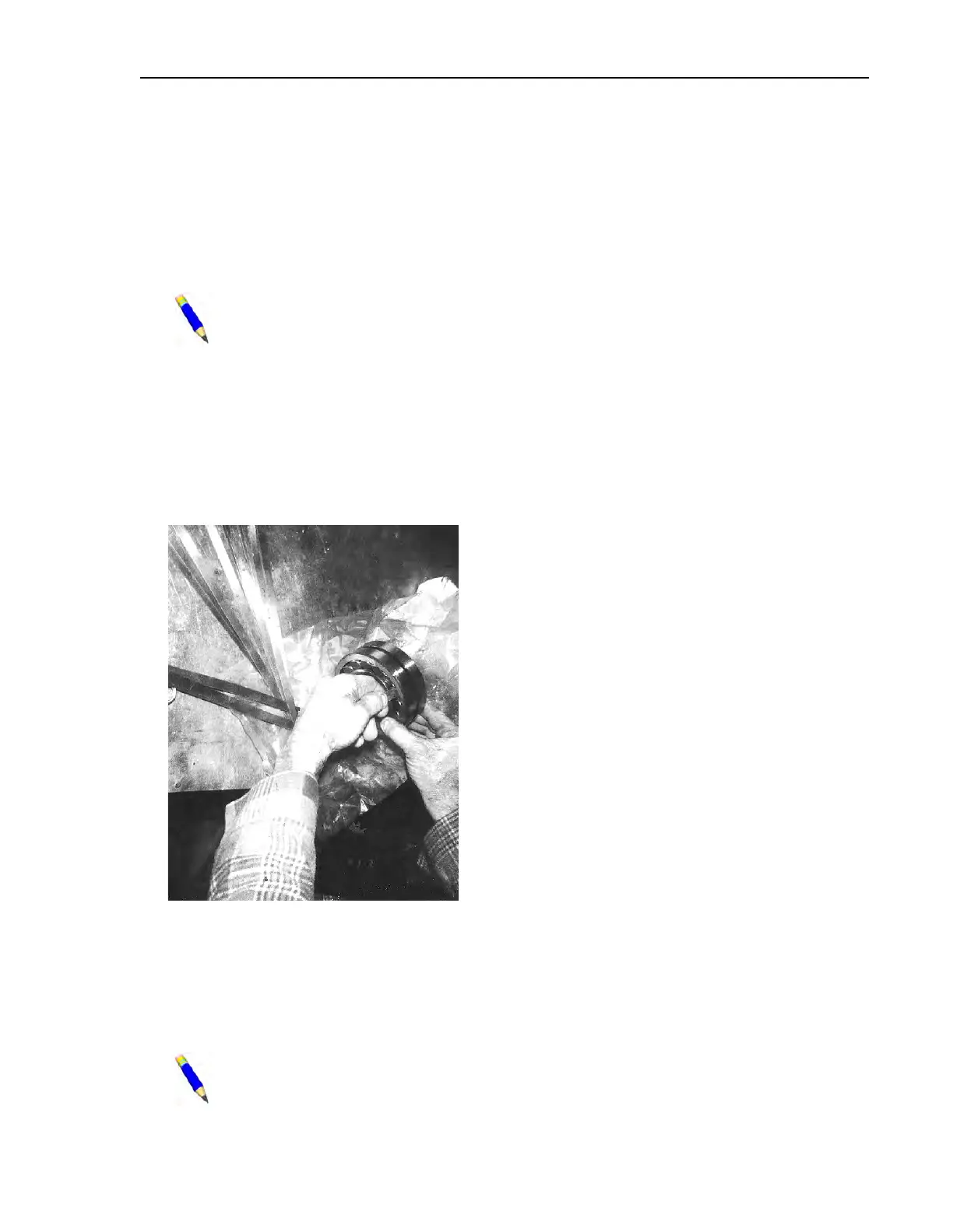
4. When you are ready to proceed (and not before), remove the new bearing from it’s box or pro-
tective wrapping. Do not attempt to clean the bearing or wash out the preservative coating.
On a clean work surface, stand the bearing on edge and insert a .003 feeler gauge into the
bearing as shown in Figure 38 . The gauge should be inserted just inside the outer race be-
tween two rollers and worked through to the opposite row of rollers. Rotate the inner race of
the opposite row so that the end of the feeler gauge is caught between a roller and the outer
race.
Figure 38. Measuring Bearing Unmounted Clearance (bridge for 42" machine shown)
5. Try to pull the gauge straight out. If it comes out, increase the size of the gauge by .001". If it
does not come out, decrease the gauge by .001". The thickest feeler gauge that will come out
is the unmounted internal clearance of the bearing.
6. Compare the measured clearance with the “Unmounted Clearance” in Table 24: Table of
Bearing Clearances, page 74 . If the measured clearance is not within the range shown, do not
use the bearing. Contact your bearing supplier for an exchange.
NOTE: The clearances listed in the chart are industry standards and therefore apply
to all brands of bearings supplied by Milnor
®
. If other sources of bearings are used, re-
fer to the manufacturer’s instructions for proper clearances.
Drive Assemblies