Pellerin Milnor Corporation 93
9. Refer to the illustration above. Ensure that the edges of the retainers (Item 4) meet but do not
overlap. Tighten the bolts (Item 5) in an alternate pattern. Constantly check assembly rotation.
Use only hand wrenches. If binding occurs, loosen the bolts and repeat.
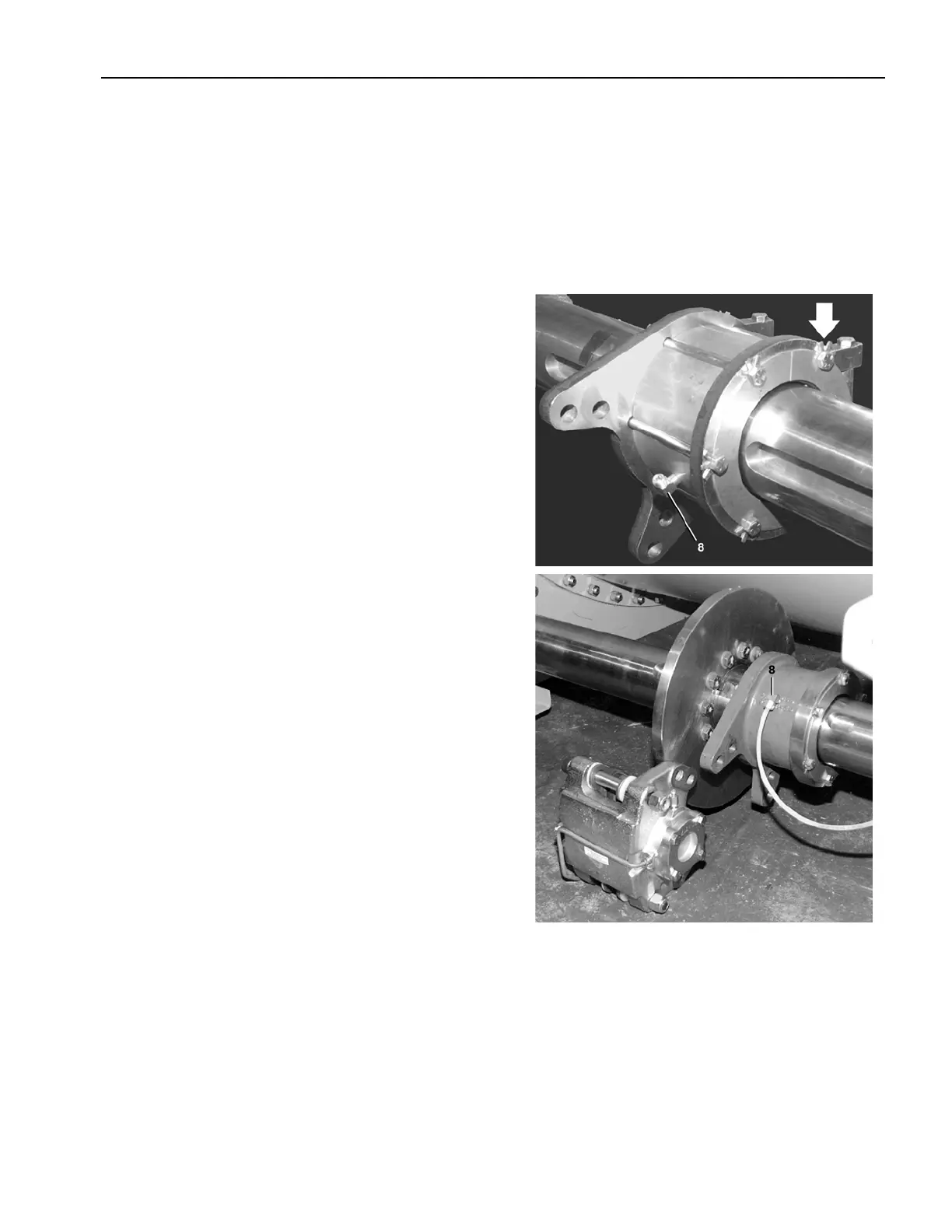
10. With all bolts tightened rotate the assembly. Bend
the star tabs (large arrow) on the retainers. The
assembly should continue to rotate freely.
11. Assemble fittings (Item 8) and tubing for grease
supply line. Refer to document BPWG6I08 for
the lower disk brake shown in this illustration.
Assembly Procedure
5 Sheets
6044SR2, 72044SR2/SR3
Drive Assemblies