A7™ Service Manual 046-006272-00 2 - 17
Installation Guide Assembly
NOTE: Use VAC when EVAC is not available. The knob on the top of the
scavenger is meant to adjust the flow from the EVAC. When the knob is
fully closed it does not need to completely shut off flow.
38. Plug the mains cable into a grounded socket. Power up the A7 by turning the main power
switch (located on the front of the A7) to the ON position. Wait until the LCD display provides
information about the leak test. Observe that the start-up self-test is successful. Do not connect,
disconnect or move the breathing circuits or breathing bags while the self-test is in process.
39. Mount the monitors and arms per instructions in the monitoring kit.
WARNING: Use only Mindray-approved monitors and arms with the A7.
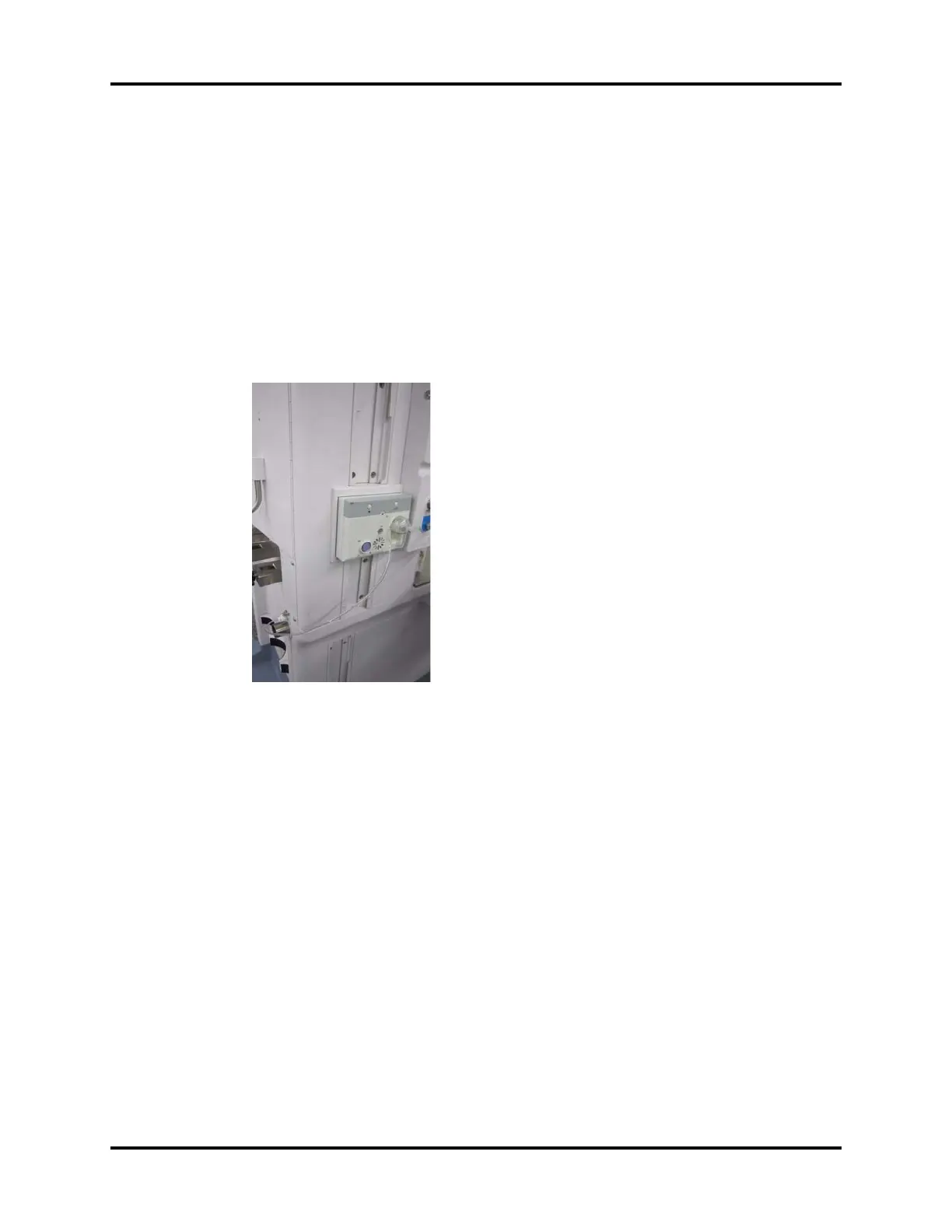
40. Install the gas module into the module rack on the left side of the unit.
FIGURE 2-26
41. Connect Hose (P/N: 115-015457-00) to the outlet of the gas module and to the Colder fitting at
the back of the A7. Place the unused hose in the bottom drawer.
42. Place the following parts into the bottom drawer:
• A7 Operating Instructions (P/N: 046-004667-00)
• Washer, Seal (P/N: 0348-00-0185)
• AGSS 3 ways connector assembly (PN: 115-026796-00)
• Suction filter (PN: 082-001327-00)
43. Hang the Pre-operative Checkout List (P/N: 046-002590-00) and the Auxiliary O2/AIR Reference
Card (P/N: 046-002591-00) to the handle of the A7 unit.
44. Mount the tank wrench on the rear of the A7 so that it can be used to open or close each
cylinder without disconnecting it from the machine.