A7™ Service Manual 046-006272-00 5 - 77
Repair and Troubleshooting Sensors and Valves Problems
5.4.10 Basal Flow Adjustment of O2 Needle Valve
1. Disconnect the #137 tube from the O2 needle valve on the anesthesia machine and connect
the tube to the inlet of the test needle valve assembly. Connect the outlet of the test needle
valve with the flow analyzer as show below(FIGURE 5-67).
FIGURE 5-67
2. Remove the two M3X3 set screws on the needle valve spacing turntable. Adjust the O2 needle
valve assembly so that the flow of flow analyzer is 1.1±0.1L/min (try to be close to 1.1L/min as
much as possible to make sure the requirement is satisfied repeatedly).
3. Operate as follows with the flow kept unchanged:
a. Rotate the turntable to let the bulge touch the spacer pin (located on the trigger switch
mounting block and trigger rod), see FIGURE 5-68).
FIGURE 5-68
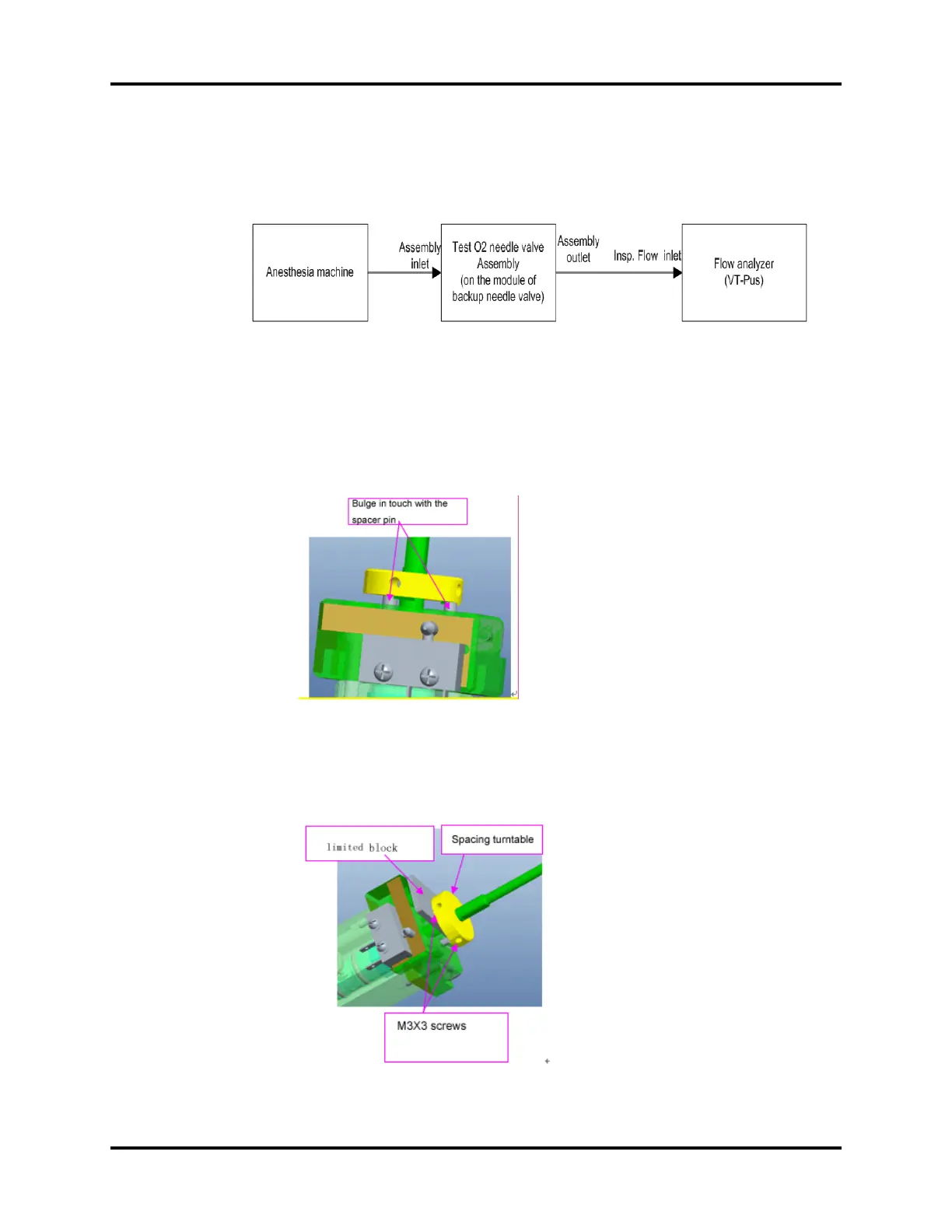
b. Plug the assembling limited block (0632-J07) for needle valve in the middle. Fix the needle
valve spacing turntable with two M3X3 set screws (dispensing thread sealant 243), see
FIGURE 5-69. The screws are located inside the two threaded holes vertical to each other,
The tightening torque is 4 to 5kgf.cm.
FIGURE 5-69