EasyManuals Logo

Mindray A7 Service Manual

Mindray A7
482 pages
To Next Page IconTo Next Page
To Previous Page IconTo Previous Page
Page #99 background imageLoading...
Page #99 background image
A7â„¢ Service Manual 046-006272-00 1 - 85
Theory of Operation Electrical Flow Control System
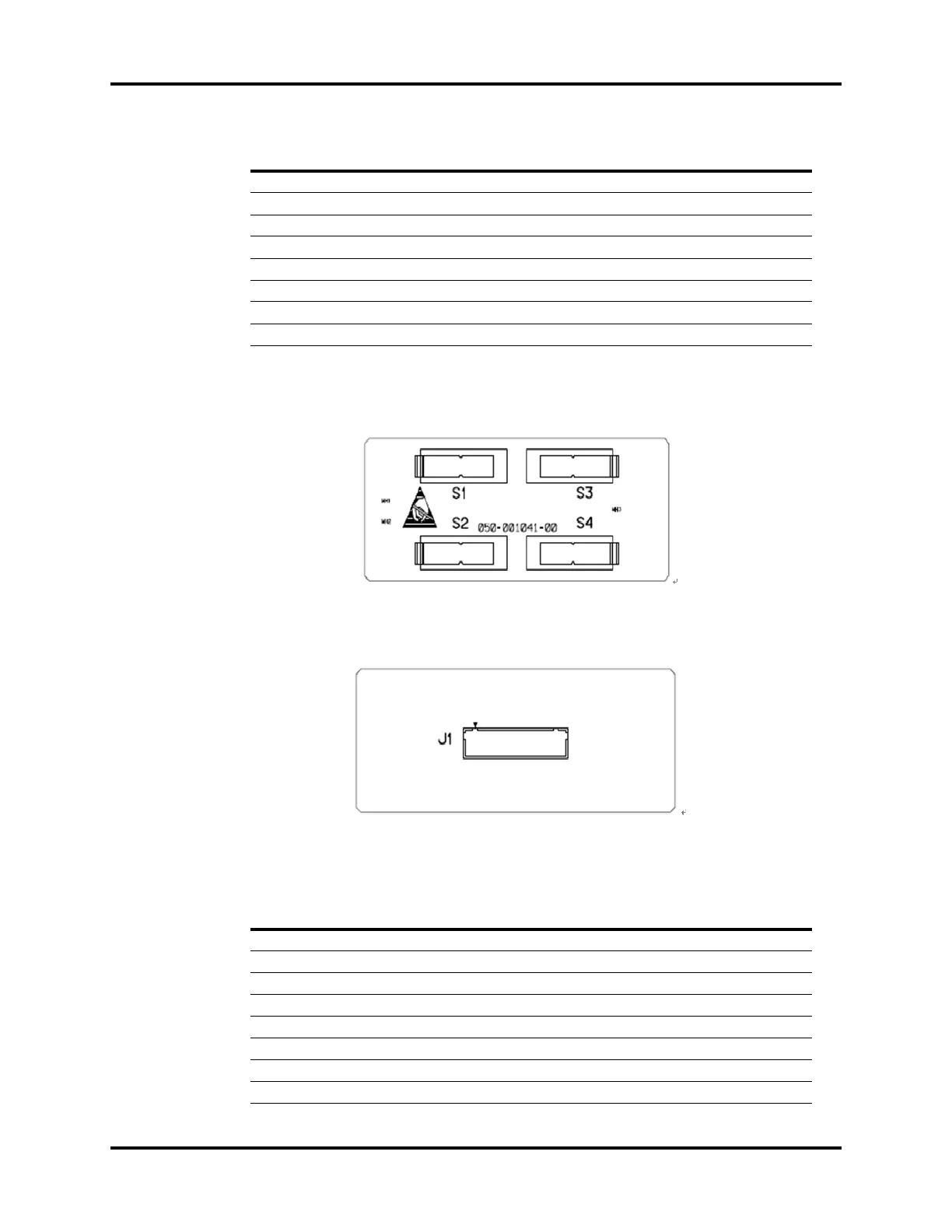
1.8.2 BFCS Position Board
FIGURE 1-87 BFCS Position Board, Top View
FIGURE 1-88 BFCS Position Board, Bottom View
EFCS Monitoring Board Interface, J1
23 BFCS_SWITCH4_IN BFCS Position Switch 4
24 GND Ground
25 O2_SWITCH O2 Supply Pressure Switch
26 GND Ground
27 Air_SWITCH AIR Supply Pressure Switch
28 GND Ground
29 N2O_SWITCH N2O Supply Pressure Switch
30 GND Ground
PIN NAME FUNCTION
PIN NAME FUNCTION
1 BFCS_Switch1 BFCS Position Switch 1
2GND Ground
3 BFCS_Switch2 BFCS Position Switch 2
4GND Ground
5 BFCS_Switch3 BFCS Position Switch 3
6GND Ground
7 BFCS_Switch4 BFCS Position Switch 4
8GND Ground

Table of Contents

Other manuals for Mindray A7

Questions and Answers:

Question and Answer IconNeed help?

Do you have a question about the Mindray A7 and is the answer not in the manual?

Mindray A7 Specifications

General IconGeneral
TypeAnesthesia Workstation
BrandMindray
ModelA7
Display15-inch color touchscreen
Oxygen FlushYes
Gas InletsO2, N2O, Air
Ventilation ModesSIMV, PSV
Breathing SystemIntegrated
Gas MonitoringO2, CO2, N2O
Monitoring ParametersFiO2
CO2 MonitoringMainstream or Sidestream
Power Supply100-240 V, 50/60 Hz

Related product manuals