EasyManuals Logo

Mindray A7 Service Manual

Mindray A7
482 pages
To Next Page IconTo Next Page
To Previous Page IconTo Previous Page
Page #453 background imageLoading...
Page #453 background image
A7â„¢ Service Manual 046-006272-00 7 - 3
Replacement Parts Introduction
7.1.2 Diagrams and Tables
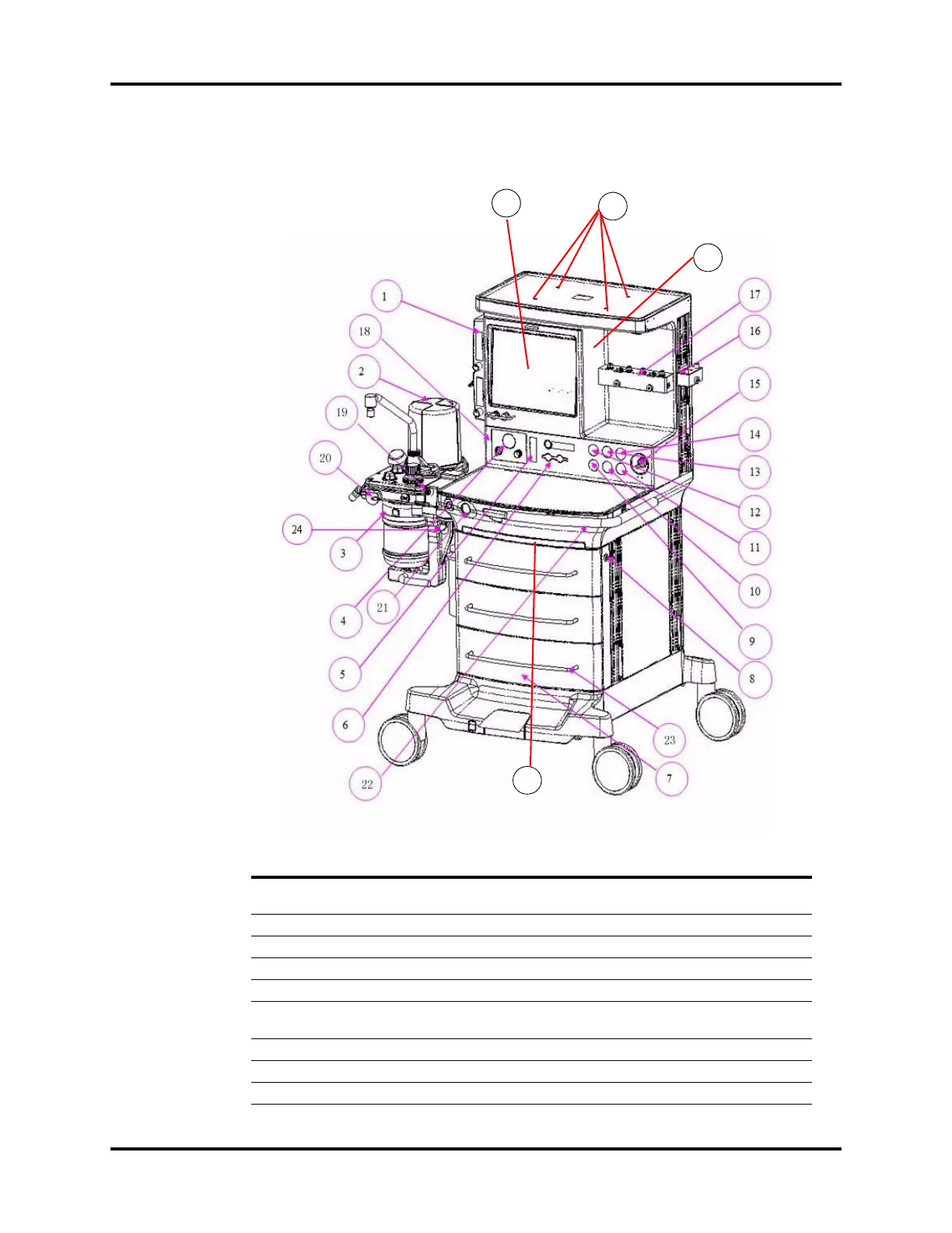
7.1.2.1 A7 Structure
FIG.NO. DESCRIPTION PART NUMBER
1 Auxiliary Gas Outlet Assembly
115-018165-00(FDA)
115-018166-00(Canadian)
2 Breathing circuit unit FRU(A7) 115-027250-00
3 CO2 Bypass Assembly, A series 115-036378-00
4 Vacuum control panel assembly (A7) 115-015246-00
5 Total flowmeter 115-014479-00
6BFCS assembly
115-030000-00(FDA)
115-030001-00(Canadian)
7 Drawer Assembly 115-034451-00
8 Drawer Lock A-series 115-023320-00
/ Drawer rail 031-000041-00
25
27
26
28

Table of Contents

Other manuals for Mindray A7

Questions and Answers:

Question and Answer IconNeed help?

Do you have a question about the Mindray A7 and is the answer not in the manual?

Mindray A7 Specifications

General IconGeneral
TypeAnesthesia Workstation
BrandMindray
ModelA7
Display15-inch color touchscreen
Oxygen FlushYes
Gas InletsO2, N2O, Air
Ventilation ModesSIMV, PSV
Breathing SystemIntegrated
Gas MonitoringO2, CO2, N2O
Monitoring ParametersFiO2
CO2 MonitoringMainstream or Sidestream
Power Supply100-240 V, 50/60 Hz

Related product manuals