EasyManuals Logo

Mindray A7 Service Manual

Mindray A7
482 pages
To Next Page IconTo Next Page
To Previous Page IconTo Previous Page
Page #345 background imageLoading...
Page #345 background image
A7â„¢ Service Manual 046-006272-00 5 - 71
Repair and Troubleshooting Sensors and Valves Problems
5.4 Sensors and Valves Problems
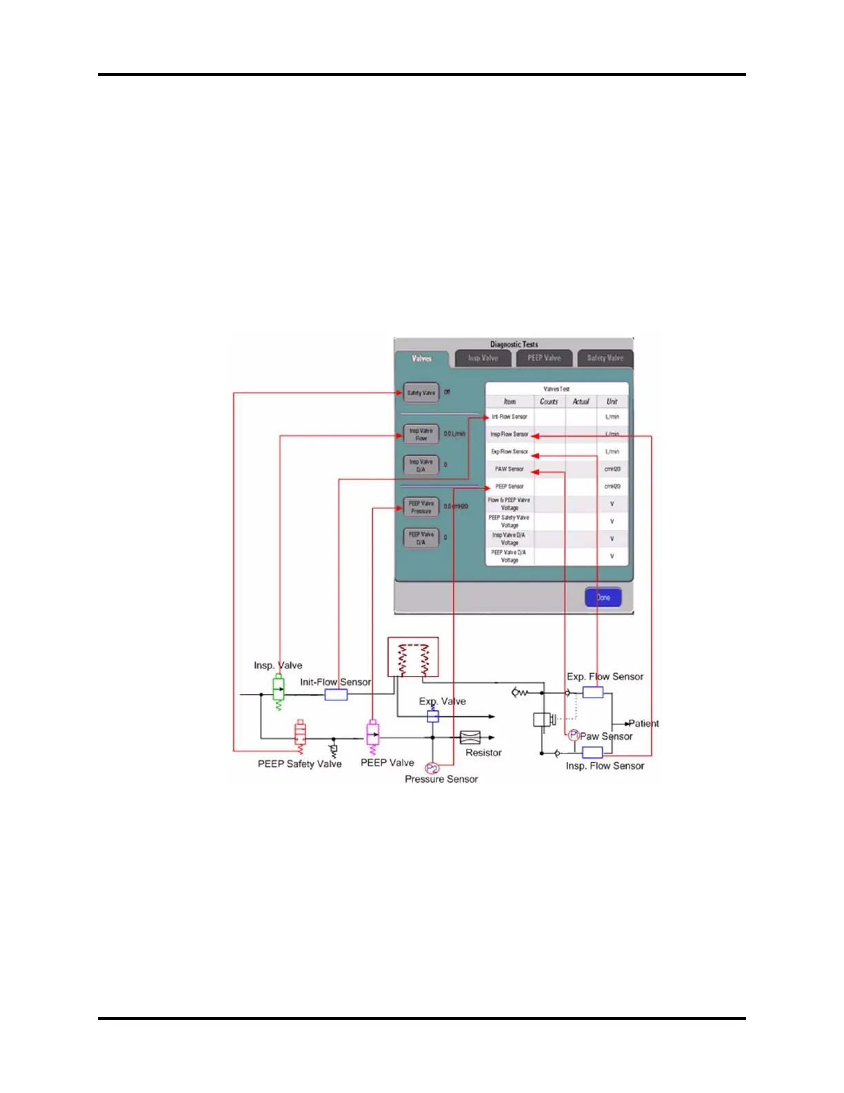
To use Diagnostic Tests to troubleshoot the sensors or valves related failures, you must be familiar
with the one-to-one correspondence between the menu options on the Diagnostic Tests screen and
the actual pneumatic circuit and hardware components.
5.4.1 Correspondence with Pneumatic Circuit Components
The following figure shows the one-to-one correspondence between the sensors & valves on the
valves-test tool screen and the actual components in the pneumatic circuit diagram.
FIGURE 5-65
5.4.2 Correspondence with Hardware Components
The following figure shows how the sampling lines of the sensors are actually connected on the
ventilator control board.

Table of Contents

Other manuals for Mindray A7

Questions and Answers:

Question and Answer IconNeed help?

Do you have a question about the Mindray A7 and is the answer not in the manual?

Mindray A7 Specifications

General IconGeneral
TypeAnesthesia Workstation
BrandMindray
ModelA7
Display15-inch color touchscreen
Oxygen FlushYes
Gas InletsO2, N2O, Air
Ventilation ModesSIMV, PSV
Breathing SystemIntegrated
Gas MonitoringO2, CO2, N2O
Monitoring ParametersFiO2
CO2 MonitoringMainstream or Sidestream
Power Supply100-240 V, 50/60 Hz

Related product manuals