A7™ Service Manual 046-006272-00 6 - 49
Repair and Disassembly Disassemble the Assemblies
6.2.8 Remove the Panel of Pressure Gauges
1. Open the service door and refer to “Open the Service Door” on page 6-3.
2. Disassemble the rear panel and refer to “Remove the Rear Cover Plate Assembly” on page 6-29.
3. Remove the module rack cabinet assembly and refer to “Remove the Module Rack Assembly” on
page 6-47.
4. Disconnect the cables from the system switch, indicator board, and auxiliary needle valve
extension mechanism.
5. Unplug the related tubes from the gas supply pressure gauge and system switch assembly of
the instrument panel and unplug one end of the tubes from the total flowmeter assembly and
needle valve module.
6. Remove the three copper pipes on the high-pressure pressure gauges from cylinder bracket
assembly.
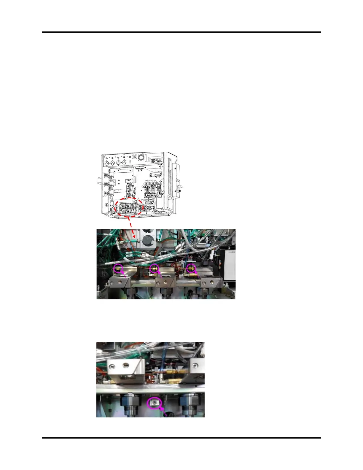
FIGURE 6-108
7. To remove the work surface cover plate assembly, refer to “Remove the Work Surface Cover
Plate” on page 6-28.
8. Unscrew one screw from the back of the machine to remove the BFCS support bar.
FIGURE 6-109