Gas Flow Theory of Operation
1 - 20 046-006272-00 A7™ Service Manual
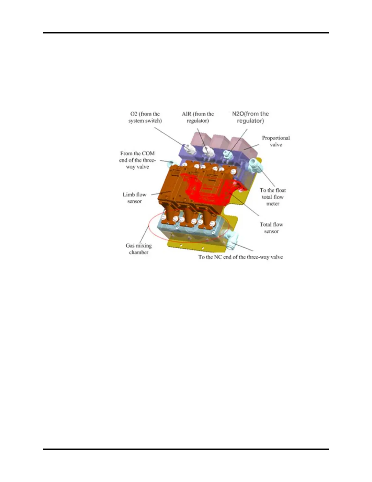
The following figure shows the pneumatic block structure of the EFCS. The three gases, after being
regulated, go through the proportional valves, through limb sensors, through the gas mixing
chamber, and into the three-way valve. Then, the gas mixture returns to the total flow sensor and
finally output to the mechanical float flow meter. Hardware boards and various hardware interfaces
are available under the pneumatic block.
FIGURE 1-13
1.3.4.5 Flow Control System - BFCS
The BFCS of the A7 comprises two mechanical needle valves that are used to control the flow of the
O2 and air limbs and control the O2-AIR ratio. After passing through the two independent check
valves in the mixing chamber, the gases of the two limbs are mixed and finally output.
1.3.4.5.1 BFCS - Motor
The motor of the BFCS provides the force for withdrawing the backup needle valve assembly, and
locates and fastens the backup needle valve assembly by using electromagnet.