Home
Mindray
Medical Equipment
A7
Page 473
Mindray A7 - Page 473
482 pages
Manual
Save Page as PDF
To Next Page
To Next Page
To Previous Page
To Previous Page
Loading...
A7™ Ser
vice Manual
046-006272-00
7 - 23
Replacement Parts
Introduction
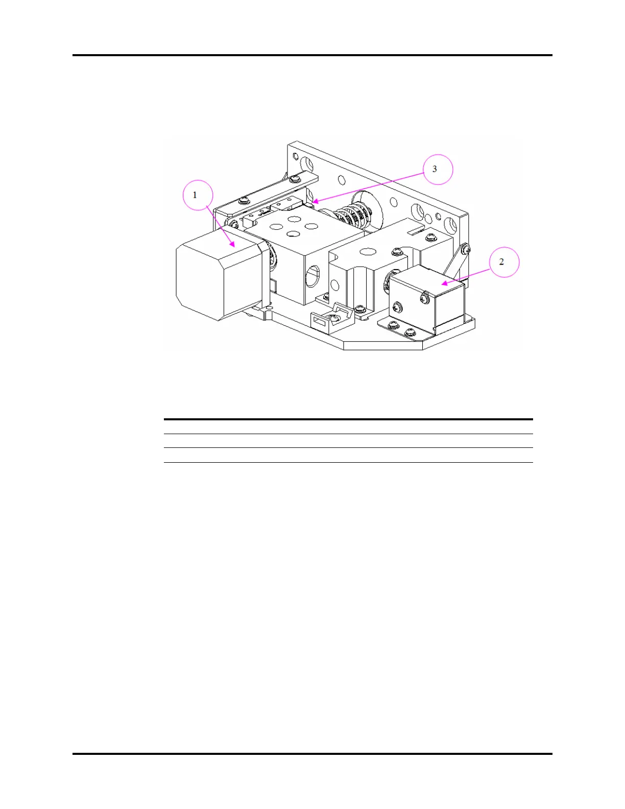
7.1.2.17
BFCS Motor assembly
FIG.NO
.
DESCRIPTION P
ART
NUMBER
1
B
FCS drive assembly
115-029847-00
2
S
olenoid 115-018144-00
3
B
FCS position swit
ch board
051-001286-01
472
474
Table of Contents
Main Page
Default Chapter
5
Table of Contents
5
Foreword
11
Warnings, Cautions, and Notes
11
Warnings
11
Cautions
12
Notes
13
Theory of Operation
15
Introduction
16
Electrical and Pneumatic Connections
18
Electrical Connections
18
Pneumatic Connections (A7)
21
Connections between Pneumatic Circuit, Breathing System and Ventilator Control Board
24
Gas Flow
26
Pneumatic Circuit Diagram
26
Parts List
27
Key to Symbols
28
Description
28
Anesthesia System Components
56
Auxiliary Outlets
56
Work Light Board
56
The Breathing System
58
Brief Introduction
58
Automatic Mode, Inspiration
58
Automatic Mode, Expiration
59
Manual Mode, Inspiration
59
Manual Mode, Expiration
60
Pneumatic PEEP
61
Ventilator in Standby
61
Breathing System Components
61
Ventilator UI
63
Display
63
CPU Board
71
Ventilator Control and Drive
74
Mother Board
74
Ventilator Control and Drive Board
84
Battery
91
Infrared Communication Board
93
Anesthesia Signal Interface Board
94
Breathing System Heater
95
Electrical Flow Control System
95
EFCS Monitoring Board
95
BFCS Position Board
99
Total Flow Meter Backlight Board
100
Air Flow Sensor Interface Board
100
Nitrous Oxide Flow Sensor Interface Board
102
O2 Flow Sensor Interface Board
103
Ventilator Pneumatic- O2 Drive Gas
105
Ventilator Pneumatic Drive
105
Drive Pressure-High Pressure Regulator (200 Kpa, 29 Psi)
105
Drive Gas Assembly
105
Tube Color Coding
105
Installation Guide
107
Preparation - Additional Material Required
108
Assembly
109
Unpacking and Setup
109
Breathing System and Breathing System Accessories and Checkout Procedures
124
Vaporizers (if Available)
124
Monitoring Products Mounting and Electrical Connection (if Available)
125
Functional Tests
126
Breathing System Leak Test
126
Automatic Backup Flow Control Test
133
Display Setup Check
136
Calibrate the AG Module
136
Gas Module Verification
138
Gas Delivery System Tests
138
Pneumatic Leak Tests
141
Line Pressure Gauges Accuracy Test
141
N2O Cylinder Leak Test
141
O2 Cylinder Leak Test
141
AIR Cylinder Leak Test
142
Line Pressure Leak Tests
142
Breathing System Checks
144
Waste Gas Scavenger Test (if Available)
144
Internal Gas Connections Test
144
Drive Gas Pressure Loss Alarm, N2O Cutoff Test
148
Performance Verification
149
Manual Mode Ventilation Test
149
APNEA Alarm Test
149
Alarm Silence Test
149
VCV Adult Ventilation Mode Test 2
150
VCV Child Ventilation Mode Test
151
Airway Disconnect Alarm Test
152
PCV Adult Ventilation Mode Test
152
Pressure Support (PS) Ventilation Mode Test
153
Alarms and Fail Safe Functions
154
Set up
154
Low O2 Alarm Test
154
High O2 Alarm Test
154
Peak Pressure Alarms Test
155
Minute Volume Alarm Test
155
Miscellaneous Tests
156
Test the Line Voltage Alarm
156
Top Light and Auxiliary Light Test
156
Touchpad Test
156
Module Rack Functional Test
156
Vaporizer Interlock Test
157
For 2 Vaporizer Mount
157
For 3 Vaporizer Mount
157
Vaporizer Accuracy Test
158
Suction Regulator Test
158
Electrical Tests
159
Auxiliary Electrical Outlet Test
159
Electrical Safety Inspection Test
159
Electrical Safety Inspection Form
159
Periodic Maintenance
161
Maintenance Schedule
162
Periodical Maintenance Consumable Parts Kits
162
Periodical Maintenance Schedule
162
Checklist before Surgery
163
Visual Inspection Checklist
164
List of Periodic Maintenance Parts to be Replaced and Checked
164
Battery Maintenance and Replacement
168
Functional Tests
168
Breathing System Leak Test
169
Automatic Backup Flow Control Test
176
Check the AG Module Accuracy
180
Gas Module Verification
181
Gas Delivery System Tests
181
Check the Sensor Zero Point
184
Check the Flow Sensor Accuracy
185
Check the Pressure Sensor Accuracy
188
Total Flow Sensor Self Test
193
Pneumatic Leak Tests
193
Line Pressure Gauges Accuracy Test
193
N2O Cylinder Leak Test
194
O2 Cylinder Leak Test
194
AIR Cylinder Leak Test
194
Line Pressure Leak Tests
195
Breathing System Checks
197
Waste Gas Scavenger Test (if Available)
197
Internal Gas Connections Test
197
Drive Gas Pressure Loss Alarm, N2O Cutoff Test
200
Performance Verification
201
Manual Mode Ventilation Test
201
APNEA Alarm Test
201
Alarm Silence Test
201
VCV Adult Ventilation Mode Test
202
VCV Child Ventilation Mode Test
202
Airway Disconnect Alarm Test
203
PCV Adult Ventilation Mode Test
203
Pressure Support (PS) Ventilation Mode Test
204
Alarms and Fail Safe Functions
204
Set up
204
Low O2 Alarm Test
205
High O2 Alarm Test
205
Peak Pressure Alarms Test
205
Minute Volume Alarm Test
206
Miscellaneous Tests
207
Test the Line Voltage Alarm
207
Top Light and Auxiliary Light Test
207
Touchpad Test
207
Module Rack Functional Test
207
Vaporizer Interlock Test
208
For 2 Vaporizer Mount
208
For 3 Vaporizer Mount
208
Vaporizer Accuracy Test
209
Suction Regulator Test
209
Electrical Tests
210
Auxiliary Electrical Outlet Test
210
Electrical Safety Inspection Test
210
Electrical Safety Inspection Form
211
Calibration
213
Introduction
214
Calibration Warnings, Precautions, and Notes
214
Warnings
214
Cautions
214
Notes
215
System Calibration
215
Flow Calibration (User)
216
Flow Calibration (Service)
220
Pressure Calibration (Service)
242
Pressure and Flow Zeroing (Service)
257
EFCS Zeroing (User)
261
Total Flow Sensor Calibration (Factory)
265
Calibrate the AG Module
268
Cylinder Yoke Regulator Calibration4
269
Adjust the Back Pressure Valve
272
Repair and Troubleshooting
275
Troubleshooting Guidelines
276
Identify the Problem
276
Avoid Shorting Component Leads Together
276
Use the Proper Equipment
276
Clean up the Repair Area
276
Technical Alarms Check
277
Startup Alarm Messages
278
CPU Board Runtime Alarm
282
Power Board Runtime Alarm
282
Runtime Alarms of Flow Sensor Board
284
Ventilator Control Board Runtime Alarm
290
Real-Time Alarms of External AG Module
293
Runtime Alarms of Internal AG Module
296
Pneumatic Circuit System Problems
297
Tools for On-Site Maintenance
297
Gas Supplies and Drive Gas
306
Anesthetic Gas Delivery System
315
Breathing System
327
Tidal Volume
342
Sensors and Valves Problems
345
Correspondence with Pneumatic Circuit Components
345
Correspondence with Hardware Components
345
Preparations before Using Diagnostic Tests
346
Zero Points of Flow & Pressure Sensors Problems
346
Connections and Measurement of the Flow Sensors Problems
347
Connections and Measurement of the Pressure Sensors Problems
347
Opening State of the Inspiratory Valve Problems
349
Opening States of the PEEP Safety Valve Problems
349
Opening State of the PEEP Valve Problems
350
Basal Flow Adjustment of O2 Needle Valve
351
Hardware and Electrical Problems
353
Software Update and Software Configuration Activation
355
Repair and Disassembly
359
Prepare for Disassembly
360
Tools
360
Preparations
360
Bleed Gas Pressure
360
Disassemble the Assemblies
361
Disassemble the Internal Assemblies of the Machine Upper Half
361
Disassemble Hardware Box
372
Disassemble the Work Surface
385
Disassemble the Auxiliary Work Surface
385
Disassemble the Display
396
Remove the Module Rack Assembly
405
Remove the Module Rack Fan
406
Remove the Panel of Pressure Gauges
407
Disassemble the Vacuum Suction Related Assembly
415
Remove the Auxiliary Gas Outlet Assembly
417
Remove the Rotating Block of Breathing Circle
418
Remove the AGSS Assembly
419
Remove the Electronically Controlled ACGO Drive Valve
420
Remove the Built-In Anesthesia Module
421
Remove the ACGO Assembly (Electronically Controlled)
423
Remove Anesthesia Module Inlet Pipeline Assembly
424
Disassemble the Base Assembly
425
Remove the Breathing Tubes
429
Disassemble the Breathing System
429
Remove the Flow Sensor
430
Remove the Manual Bag
431
Remove the Absorbent Canister
432
Remove the CO2 Bypass Assembly
434
Remove the Prepak Handle
435
Remove the Contact Switch of the L-Shaped Handle
436
Remove the Patient Circle Assembly
437
Remove the Bellows Assembly
438
Remove the Pop-Off Valve Assembly
439
Disassemble the Expiratory/Inspiratory Check Valve Assemblies
440
Remove the Water Collection Cup
441
Remove the Airway Pressure Gauge
442
Remove the Bag Arm
442
Remove the Back Upper Cover and Back Lower Cover Assemblies
443
Remove the Front Upper Cover, Median Plate and Front Lower Cover Assemblies
445
Disassemble the Automatic/Manual Ventilation Switch Assembly
448
Remove the APL Valve Assembly
450
Replacement Parts
451
Introduction
452
Ordering Replaceable Parts
452
Diagrams and Tables
453
Warranty
479
Warranty Statements
480
Disclaimers
481
Manufacturer's Responsibility
481
Phone Numbers and How to Get Assistance
481
Other manuals for Mindray A7
Operating Instructions
312 pages
Related product manuals
Mindray A9
424 pages
Mindray A8
424 pages
Mindray A3
436 pages
Mindray A5
436 pages
Mindray TE Air
84 pages
Mindray Accutorr V
130 pages
Mindray Accutorr 7
90 pages
Mindray accutorr plus
110 pages
Mindray Datascope AS 3000
180 pages
BeneHeart S1 Fully Automatic
78 pages
BeneHeart C2 Fully Automatic
78 pages
BeneHeart C1A Fully Automatic
78 pages