Ventilator UI Theory of Operation
1 - 52 046-006272-00 A7™ Service Manual
1.6.1.4 Other Components
The display system also includes the backlight inverter board, warningLight board, touchscreen
control board and encoder board. The backlight inverterboard provides backlight for the display; the
warninglight board is used for reporting visual alarms on the anesthesia machine; the touchscreen
control board controls the inputs through the touchscreen and sends processed touchscreen
operation information through a serial port.
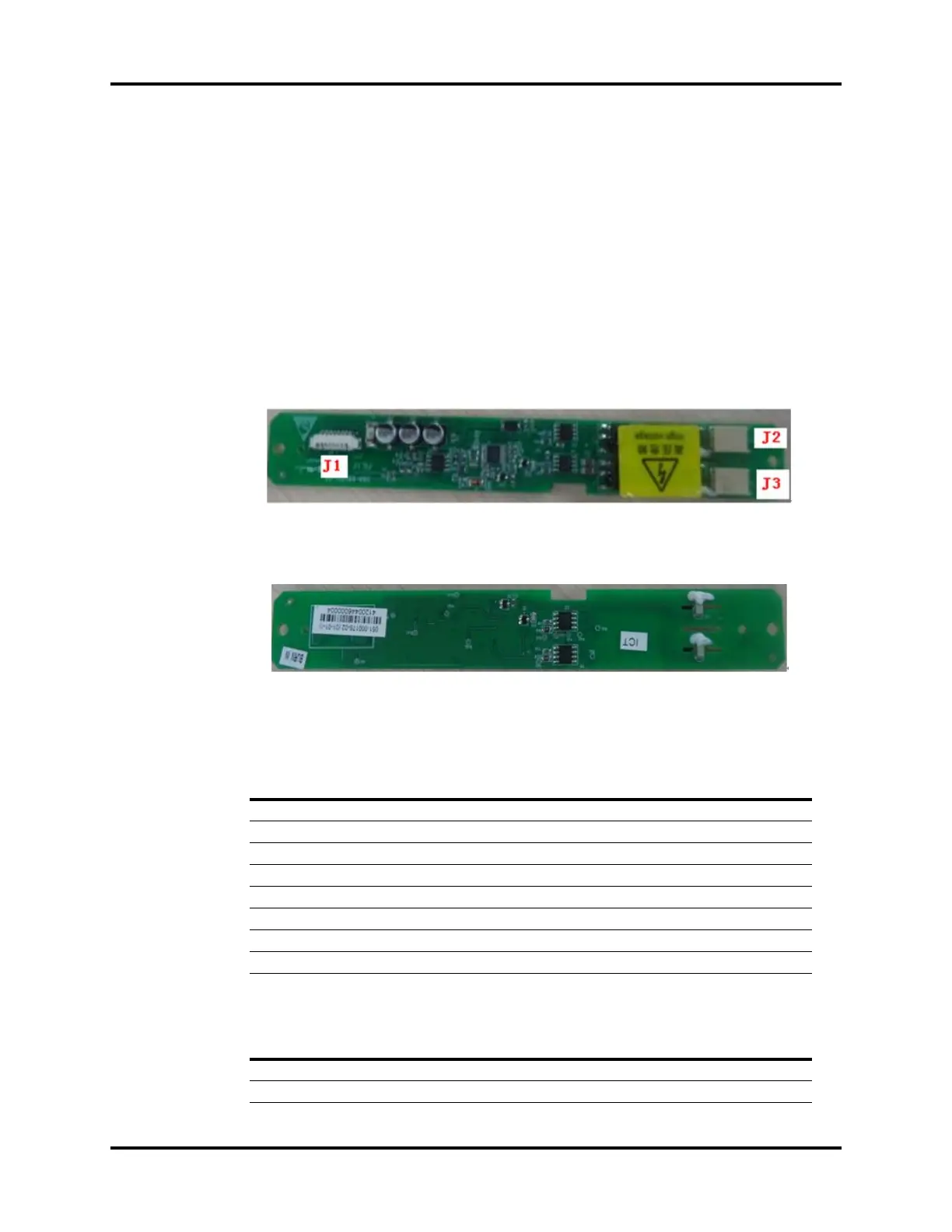
1.6.1.5 Backlight Inverter Board
NOTE: System will have a Backlight Inverter Board or a Screen Backlight
Board.
FIGURE 1-59 Backlight Inverter Board, Top View
FIGURE 1-60 Backlight Inverter Board, Bottom View
Inverter Board Interface, J1
Inverter Board Interface, J2 and J3
PIN NAME FUNCTION
1GND Ground
2GND Ground
3GND Ground
4 BL_ADJ Display Brightness Control Signal
5BL_ON/OFF Inverter Enable Signal
6 12V 12V Power Supply
7 12V 12V Power Supply
8 12V 12V Power Supply
PIN NAME FUNCTION
1 High_Voltage High-Voltage Output of the Inverter
2 Low_Voltage Low-Voltage Output of the Inverter