A7™ Service Manual 046-006272-00 1 - 55
Theory of Operation Ventilator UI
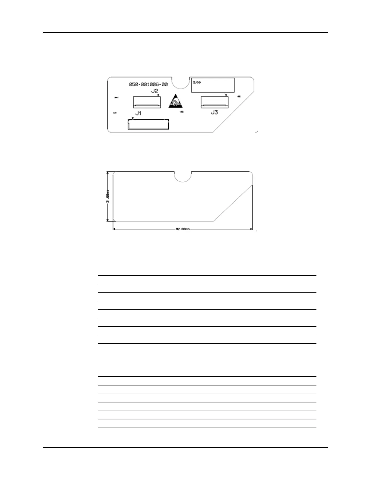
1.6.1.8 Encoder Board
FIGURE 1-65 Encoder Board, Top View
FIGURE 1-66 Encoder Board, Bottom View
Encoder Board Interface, J1
Fresh Flow Sensor Board Interface, J2 and J3
PIN NAME FUNCTION
1 VCC 5 V Power Supply (range: 4.75V~5.25V)
2GND Ground
3Encoder_A1 Output A of Encoder 1
4Encoder_B1 Output B of Encoder 1
5 Encoder_Y1 Depress of Encoder 1 (Reserved)
6Encoder_A2 Output A of Encoder 2
7Encoder_B2 Output B of Encoder 2
8 Encoder_Y2 Depress of Encoder 2 (Reserved)
PIN NAME FUNCTION
1 VCC 5 V Power Supply
2 Encoder_A Output A of Encoder
3Encoder_B Output B of Encoder
4 Encoder_Y Depress of Encoder (Reserved)
5GND Ground
6GND Ground