EasyManuals Logo

Mindray A7 Service Manual

Mindray A7
482 pages
To Next Page IconTo Next Page
To Previous Page IconTo Previous Page
Page #86 background imageLoading...
Page #86 background image
Ventilator Control and Drive Theory of Operation
1 - 72 046-006272-00 A7â„¢ Service Manual
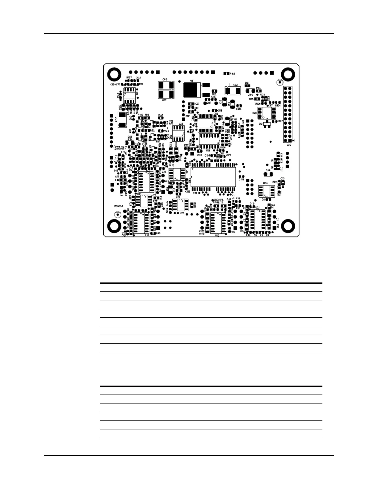
FIGURE 1-74 Monitor Signal Detection Board, Bottom View
Monitor Signal Detection Board Communication Interface, J1
Ventilator Sensor Interface, J3
PIN NAME FUNCTION
1TXD Serial Port Transmit
2RXD Serial Port Receive
3 12V 12V Power Supply
4GND Ground
5GND Ground
6 12V 12V Power Supply
7 PRST Pressure Relief Valve Control Signal
85V 5V Power Supply
PIN NAME FUNCTION
1SDA I2C Data Signal
2 SCL I2C Clock Signal
3 VT Thermal Mass Flow Sensor Temperature Signal
4 VF Thermal Mass Flow Sensor Flow Signal
5 12V Sensor Power Supply
6GND Ground

Table of Contents

Other manuals for Mindray A7

Questions and Answers:

Question and Answer IconNeed help?

Do you have a question about the Mindray A7 and is the answer not in the manual?

Mindray A7 Specifications

General IconGeneral
TypeAnesthesia Workstation
BrandMindray
ModelA7
Display15-inch color touchscreen
Oxygen FlushYes
Gas InletsO2, N2O, Air
Ventilation ModesSIMV, PSV
Breathing SystemIntegrated
Gas MonitoringO2, CO2, N2O
Monitoring ParametersFiO2
CO2 MonitoringMainstream or Sidestream
Power Supply100-240 V, 50/60 Hz

Related product manuals