Electrical Flow Control System Theory of Operation
1 - 82 046-006272-00 A7™ Service Manual
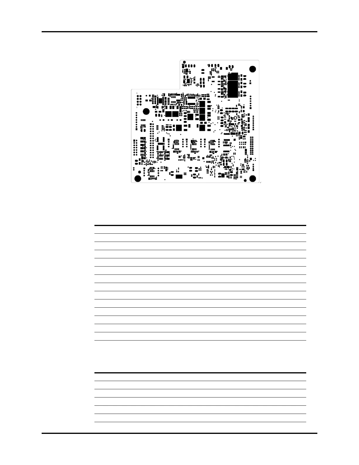
FIGURE 1-86 EFCS Monitoring Board, Bottom View
EFCS Monitoring Board Interface, J1
EFCS Monitoring Board Interface, J3
PIN NAME FUNCTION
1 VBB2 CPU Power Supply
2GND Ground
3 FPGA_VPP FPGA, NO and NC Valve Power Supply
4GND Ground
5 PROP_VALVE_VPP Proportional Valve
6GND Ground
7SAN_VPP Backup Three-Way Power Supply
8GND Ground
9 CPU_TXD_MB_BUF Communication with the CPU Board
10 GND Ground
11 CPU_RXD_MB Communication with the CPU Board
12 GND Ground
13 FPGA_RXD_MB Backup Communication Between the FPGA and the CPU Board
14 FPGA_TXD_MB_BUF Backup Communication Between the FPGA and the CPU Board
PIN NAME FUNCTION
1 VBB1 Solenoid Magnet Power Supply
2 VBB1 Solenoid Magnet Power Supply
3GND Ground
4GND Ground
5 STEP_VPP Stepper Motor Power Supply
6 STEP_VPP Stepper Motor Power Supply