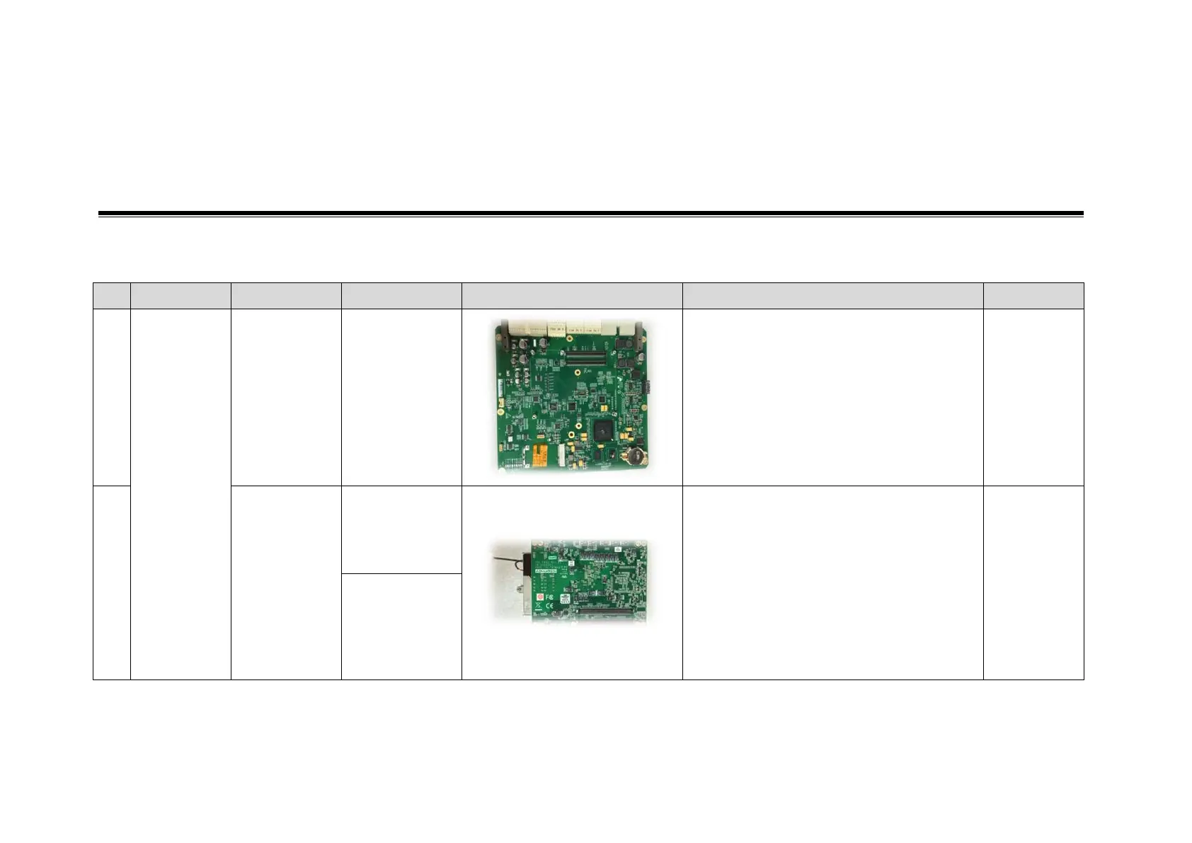
Home
Mindray
Medical Equipment
DC-70T
Mindray DC-70T Service Manual
5
of 1
of 1 rating
273 pages
Give review
Manual
Specs
To Next Page
To Next Page
To Previous Page
To Previous Page
Loading...
Field
Replaceable
Unit
8-1
8
Field Replacea
ble Unit
The det
ailed infor
mation of Field
Replaceab
le Unit is as fo
llows:
No.
Classification
Descriptio
n
Order Numb
er
Figure
Comments
Disassembly
1.
Main unit
related
PC carrier
board (spare
part)
115
-025757-
00
/
9.3.10
2.
PC Module
Assembly
115
-041021-
00
(old PC
module)
Compati
bility remarks
:
When usi
ng Old P
C module, the
software versi
on should
be:
OS version:
V3.0 or lower
Doppler v
ersion: no lim
itation
When usi
ng new PC
module, the
software versi
on should
be:
OS version:
V4.0 or hig
her
Doppler v
ersion: 02.00.
00 (Rev1907
0)
or higher
9.3.10
115
-042940-
00
(new PC
module)
106
108
Table of Contents
Default Chapter
3
Table of Contents
3
Revision History
9
Intellectual Property Statement
10
Applicable for
10
Statement
10
Customer Service Department
11
1 Safety Precautions
13
Meaning of Signal Words
13
Symbols
13
Meaning of Safety Symbols
13
Warning Labels
14
General Symbols
14
Safety Precautions
16
Electric Safety
16
Mechanical Safety
17
Personnel Safety
17
Other
17
2 Specifications
19
Overview
19
Intended Use
19
Introduction of each Unit
19
Peripherals Supported
28
Specifications
28
Dimensions & Weight
28
Electrical Specifications
28
Environmental Conditions
28
Monitor Specification
29
3 System Installation
31
Preparations for Installation
31
Electrical Requirements
31
Installation Conditions
32
Confirmation before Installation
33
Unpacking
33
Unpacking Process
33
Check
35
Installation of Main Unit
35
Open up the Monitor
36
Connecting the Power Cord
36
Connecting ECG
37
Installing Probe/Gel Holder
37
Connecting the Transducer
38
Installing Peripherals
39
Connecting the Footswitch
39
Installing a Graph / Laser Printer
39
Installing Video Printer
42
Installing a Wireless Printer
42
Position a Printer
43
Installing Barcode Scanner
44
System Configuration
45
Running the System
45
Enter Doppler
45
System Preset
46
Print Preset
47
Network Preset
47
DICOM/HL7 Preset
48
Check System Information
51
4 Product Principle
53
Hardware System Diagram
53
Ultrasound Front-End Unit
54
Probe Board
55
TR Board
55
CW Module
56
Engine Board
57
Module
58
ECG Module
59
Ultrasound Back-End Unit
59
PC Module
60
Storage Device
60
Wireless Network Module
60
PC Carrier Board
60
IO Interface Module
61
Extension and Distribution
62
Video Extension Function
62
Audio Interface
63
SATA Interface
63
USB Distribution
63
Network Interface
64
PCIE Interface Distribution
65
Other IO Extension
65
Power Supply Unit
66
AC-DC Module
67
DC-DC Module
68
PHV Module
68
Time Sequence of Power-On
68
User Interaction Unit
68
Control Panel Assembly
68
Primary Display Assembly
69
Secondary Display Assembly
69
5 Function and Performance Checking Method
71
Note
71
System Running Status
71
Running Status
71
Working Condition
71
General Exam
72
Check Flow
72
Checking Content
72
Function Checking
75
Checking Flow
75
Performance Test
81
Test Process
81
Test Content
81
6 Software Installation &Maintenance
89
Enter Maintenance
89
Set Installment
90
Software Installation/Restoration
92
Enter Windows
92
Software Maintenance
93
Export Log
93
Data Backup and Storage
93
Preset Data Management
93
Patient Data Backup and Restoration
94
Introduction on Hard Disk's Partitions
96
7 Adjustments
97
Monitor Adjustment
97
Position Adjustment
97
Brightness and Contrast Adjustment
99
Monitor Test
100
Monitor Parameter Setting
103
Touch Screen Adjustment
103
Touch Screen Brightness and Contrast Adjustment
103
Touch Screen Test
104
Control Panel Adjustment
104
Caster Adjustment
106
8 Field Replaceable Unit
107
9 Structure and Assembly/Disassembly
125
Structure of the Entire System
125
Preparation
126
Disassembly Tools Required
126
Engineers Required
126
Disassembly Requirements
126
Assembly/Disassembly
127
Display (Monitor) Assembly
128
Probe Board Assembly
129
Disassembling ECG Assembly
131
Outlet Fan
132
Disassembling Battery Assembly
133
IO Board/Wifi Board
136
Hdd
138
Electronic Assembly on the Base
140
DC Box Assembly
141
PC Assembly
142
Engine Board and TR Board
144
DVD
145
Inlet Fan
146
Motherboard
147
Control Panel Assembly
149
Face Cover Assembly of the Speaker/Speaker
154
Caster
156
Module Package
156
The Material Package of CW Assembly
158
Support Arm Assembly of the Control Panel
159
Support Arm Assembly of the Display
164
Keyboard Assembly
169
Power Input Assembly
169
Control Switch Board
171
AC Connecting Board (220 V)
171
FAN (AC-DC Fan)
172
10 Optional Installation/Assembly
173
Installing Optional Software
173
11 System Diagnosis and Support
185
General Status Indicator
185
Indicators on Control Panel
185
Display Status Indicator
186
The Status Indicator of the Batteries on IO Rear Board
186
Status of Entire Device
187
Status Indicator of Gel Warmer
187
Get Entire Device Started
188
Power-On of Entire Device Supplied by AC
189
Start-Up Process of BIOS
189
Windows Start-Up
189
Start-Up of Doppler
190
Alarming and Errors
192
Battery Error
192
Abnormal Voltage of System Power
192
Abnormal Temperature
193
Fan Error
194
PHV Error
195
Gel Warmer Abnormality
196
Other Errors
197
Self Test
197
Self Test Introduction
197
Operation Procedure of Maintenance Self Test
197
User Self Test
202
Test Report
204
12 Care and Maintenance
207
Overview
207
Tools, Measurement Devices and Consumables
207
Routine Maintenance Items
207
Cleaning
209
System Cleaning
209
Peripherals Cleaning
213
Check
213
General Check
213
System Performance Check
214
Check for Peripherals and Optional Functions
214
Mechanical Safety Inspection
216
Electrical Safety Inspection
218
13 Troubleshooting of Regular Malfunctions
219
System Cannot Power on
219
Related Modules or Boards
219
Key Points Supporting Troubleshooting
219
Troubleshooting as the System Unable to Power on
220
System Cannot Start
221
Related Modules or Boards
221
Key Points Supporting Troubleshooting
221
The System Cannot Perform Troubleshooting
221
Image Problems
222
Related Modules or Boards
222
Key Points Supporting Troubleshooting
222
Image Troubleshooting
223
Probe Socket System Malfunction
224
Related Modules or Boards
224
Key Points Supporting Troubleshooting
224
Troubleshooting of Probe Socket System
224
IO Interface System Failure
224
Key Points Supporting Troubleshooting
225
Troubleshooting of IO Interface System
226
Control Panel Failure
227
Related Modules or Boards
227
Key Points Supporting Troubleshooting
227
Troubleshooting of Control Panel
227
LCD Display Failure
228
Related Modules or Boards
228
Key Points Supporting Troubleshooting
228
Troubleshooting of the Monitor
229
ECG Module Failure
229
Related Modules or Boards
229
Key Points Supporting Troubleshooting
230
Troubleshooting for ECG Module
230
Appendix A Electrical Safety Inspection
231
Appendix B Phantom Usage Illustration
249
Appendix C Description of Self Test Items
251
5
Based on 1 rating
Ask a question
Give review
Questions and Answers:
Need help?
Do you have a question about the Mindray DC-70T and is the answer not in the manual?
Ask a question
Mindray DC-70T Specifications
General
Brand
Mindray
Model
DC-70T
Category
Medical Equipment
Language
English
Related product manuals
Mindray DC-70
295 pages
Mindray DC-70 Pro
295 pages
Mindray DC-70 Exp
295 pages
Mindray DC-7
2 pages
Mindray DC-8
287 pages
Mindray DC-T6
347 pages
Mindray DC-40
303 pages
Mindray DC-33
303 pages
Mindray DC-26
213 pages
Mindray DC-35
303 pages
Mindray DC-30
213 pages
Mindray DC-N3S
277 pages