4-4 Product Principle
Beam data sends back to the engine board via the serial and the addition from one board to another.
Engine board controls TR board via the asteroidal.
ctrl
RX
data
64ch
TX
AFE_CLK
BF_CLK
control bus
powerJTAG downstream
reset
Probe Board
reset status
present
RATE
TR Board
64ch TX/RX
slot ID
DSP FPGA
Engine Board
clock
XCVR_REFCLK
Pencil Probe
Pen Probe TX/RX
connect to TR_A slot
Adjacent TR board on
frond end side, if exists.
data bus
ATGC bus
Adjacent TR board on
back end side, if exists.
present
JTAG data
data bus
present
JTAG data
AFE_CLK
TX_CLK
BF_CLK
64ch
RX
Pen Prb
RX
switch
ctrl
ATGC
TX_CLK
data bus (from TR_A)
CW
present/ID
RX data
power
DC-DC board
scan status
PHV board
ctrl
TR
FPGA
TX circuits RX circuits
TX-RX switch
including pen probe TX-RX switch
CW mini
board
(TR_A)
Clock distribution
ATGC
Including switch
between local and bus
ctrl
Mother
Board
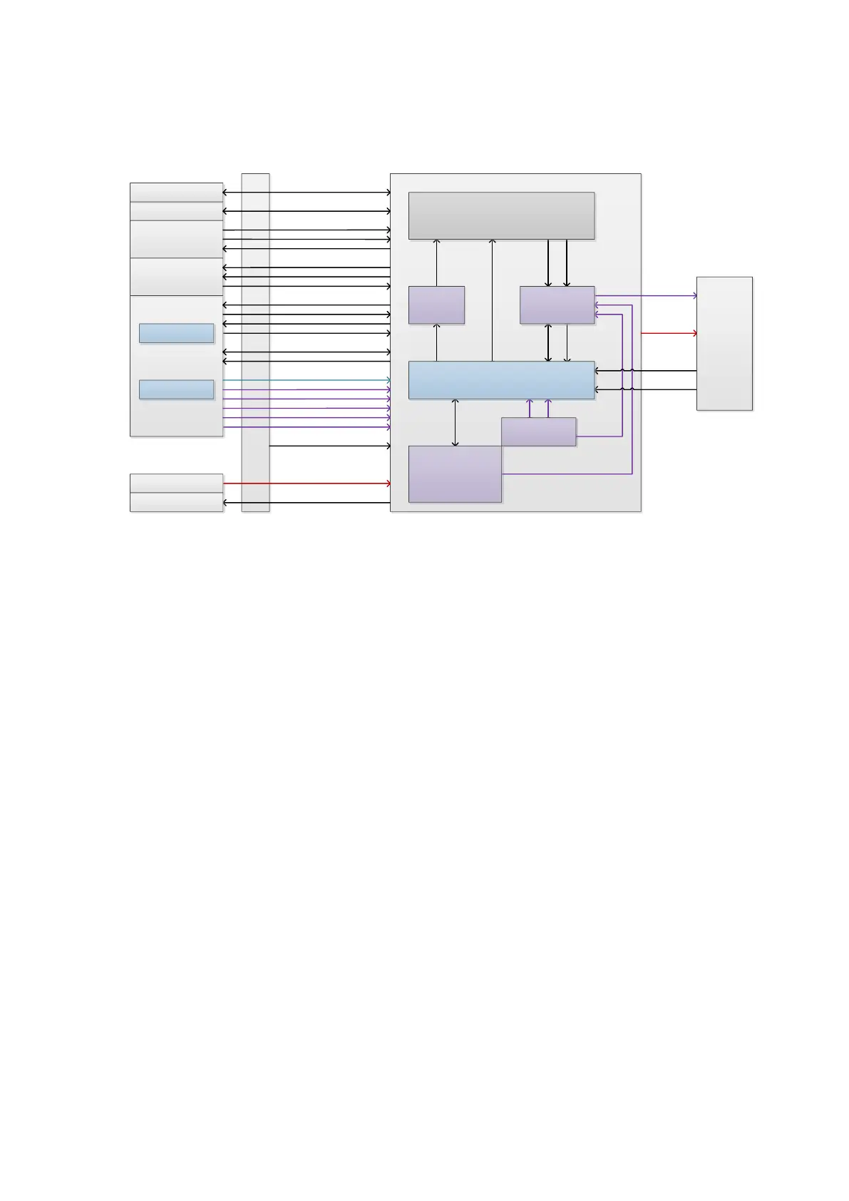
Figure 4-4 Schematic diagram of TR board
The functions of TR board:
Transmitting: in accomplishing the transmitting focus of the entire unit, TR_FPGA controls 64
channels on a single board to send high-voltage ultrasound signal to the probe.
Receiving: in accomplishing the receiving focus, TR_FPGA controls 64 channels on a single
board to receive ultrasound echo signal of the probe.
Beam data processing: is to receive the beam data which is weighted from the previous TR
board, and passes to the next TR board. Finally, it adds all beam data on array channels
together and sends it to engine board’s DSP_FPGA.
CW: it refers to the CW mini board on TR_A board. It fulfills the adjustment of CW based on
AFE plan. The adjustment result will send to TR_FPGA.
Pencil probe support: is available to fulfill the switch on TR_A board between the receiving
channel of the pencil probe and the regular receiving channel. It finally connects to CW mini
board.
Control: it is necessary to take controls to accomplish the functions, such as: Download the
parameters to TR_FPGA in real-time as DSP_FPGA controls the interface; Delay control in
transmitting; Receive the gain control of the clip, etc.
4.2.3 CW Module
CW probe is an option. The transmitting circuit of CW shares the transmitting circuit with B/Color
mode. The receiving circuit of CW is more than B/Color mode’s.
CW module of DC-70 is CW mini board. It is used to add the receiving signals of TR board and
adjust the data. The data is transmitted to TR_FPGA inside TR board. TR_FPGA recognizes CW
mini board via in-place signal and ID code.