Product Principle 4-1
4 Product Principle
4.1 Hardware System Diagram
TR
FPGA
CW
Mini Brd
DSP
FPGA
4D&TEE
Board
Pencil Probe
Connection
Engine
Board
TR_A Board
Clock
DataData
DDR
ATGC
Probe Various Signals
CPLD
Probe
Signal
Switch
Probe
Connector
A
POUT(64)
Present/ID
Probe Board
Power
Probe Management
PHV Control
Front End
Monitoring
DC-DC Board
Battery Unit
Battery
Battery
Management
AC-DC
Module
Transformer
AC
Input
TX/RX
TX/RX
Power
TX
RX
Front- End
Back- End
Power
PHV
Sampling
Scan Status
PHV
Sync
AC output
Control
PHV Control
Monitoring
PCI-E Bus
Reset
Configuration
Status
JTAG
Touch Screen Device
Hard Disk/DVD-RW
Speaker
Control Panel
Primary Display Device
Secondary Display Device Wireless Network
Digital Video Output
Audio Output
Printer
Analog Video Output
USB Ports
Wired Network
Fans
PC Module
MF FPGA
Back End Monitoring
IO Expansion
PC Unit
PC Manager
Microphone
Physiological Signal
Module
DC-DC
IO Interfaces and Devices
Communication
Reset/Control/Clocks
AC Output
for Printer and User
DC
Probe
Connector
B
Probe
Connector
C
Probe
Connector
D
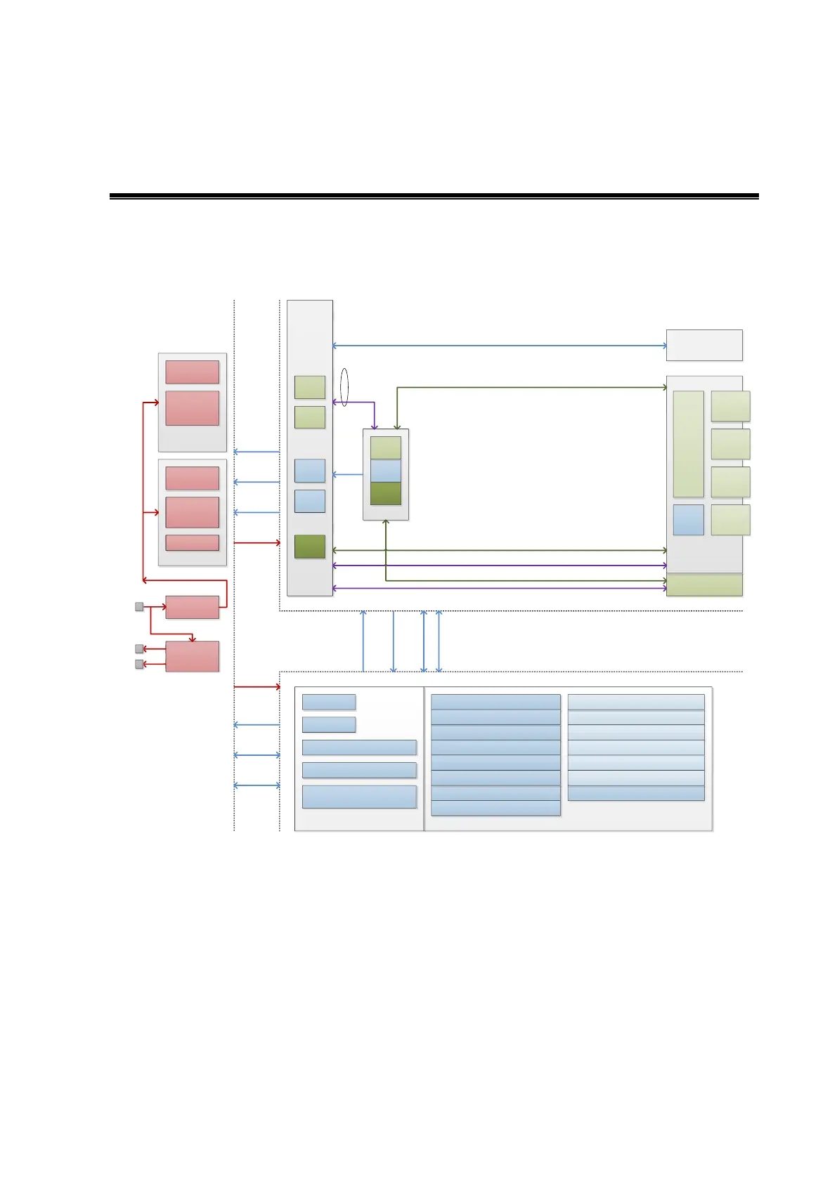
Figure 4-1 of Hardware system diagram
The ultrasound device can be divided into three units according to its functions:
Front-end unit: is in charge of the scan function of the ultrasound imaging system, and sends
the pre-processed imaging data to the back-end unit for post-process. The engine board takes
charge of front-end unit. The elements are shown above:
The uploaded data on TR64 board are wired in daisy chain and sent to the engine board.
Control interface, the clock, Rate, sub-module information management (in the place,
board ID) are all based on the engine board, which distributes to other sub-modules.
The management functions of the probe decouple the transmitting/receiving channel, and
communicate with the engine board.