A-12 Electrical Safety Inspection
ELECTRICAL SAFETY INSPECTION
7- Mains on Applied Part Leakage
The Mains on Applied Part test applies a test voltage, which is 110% of the mains voltage,
through a limiting resistance, to selected applied part terminals. Current measurements are then
taken between the selected applied part and earth. Measurements are taken with the test voltage
(110% of mains) to applied parts in the normal and reverse polarity conditions as indicated on the
display.
The following outlet conditions apply when performing the Mains on Applied Part test.
Normal Polarity;
Reversed Polarity
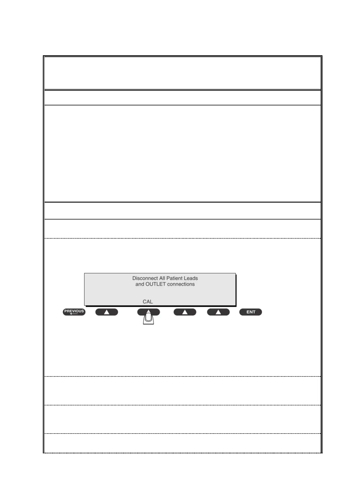
To perform a calibration from the Mains on Applied Part test, press CAL (SOFT KEY 2).
1) Disconnect ALL patient leads, test leads, and DUT outlet connections.
2) Press CAL to begin calibration, as shown:
If the calibration fails, the previously stored readings will be used until a passing calibration has
occurred. Also, the esc/stop key has no effect during calibration.
3) When the calibration is finished, the Mains on Applied Part test will reappear.
1) A 2-beep-per-second signal indicates high voltage present at the applied part terminals while a
calibration is being performed.
2) High voltage is present at applied part terminals while measurements are being taken.