18. Interface specifications
MiR250 User Guide (en) 11/2020 - v.1.3 ©Copyright 2020: Mobile Industrial Robots A/S. 201
Pin no.
Signal
name
Type Description
5 E-stop 2 Input Safety input 2.
6 Restart Input Safety input 3.
7 RST_
LAMP_24_
V
Output 24 V output for powering the lamp on the
Emergency stop box.
8 NC Not connected to the robot.
9 NC Not connected to the robot.
10 NC Not connected to the robot.
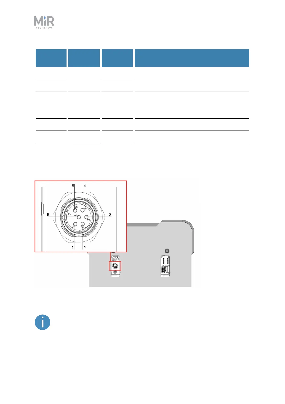
Power
Figure 18.2. Pin numbers: female connector viewed from the front (left) and wiring diagram (right).
The maximum current across pins 1 and 3 combined is 10A. You cannot
receive 10Afrom both of the pins at the same time.
 Loading...


