Chapter 4 Mx-Series Unit Description 4-
3
<Figure 4-13 Upward camera
>..............................................................................4-26
<Figure 4-14 Downward
camera>.........................................................................4-28
<Figure 4-15 Mx-Seies system ANC (Top
View)>...............................................4-31
<Figure 4-16 Automatic Nozzle Changer
(ANC)>................................................4-32
<Figure 4-17 A Type H-4C Nozzle
>................................................................4-34
Introduction
This chapter covers the structure, operation flow and main units of the Mx-
Series SMD Mounter.
This chapter describes the operation and functions of the machine and
provides detailed information along with assembly drawings, where
necessary.
This chapter includes:
• Introduction
• Structure and configuration
• Operation flow
• Unit description
− PCB Transfer System: PCB conveyer
− Component Feeding System: Feeder base, feeder, intelligent feeder
− Positioning System: XY gantry, positioning head, vision system,
automatic nozzle changer, nozzle unit
− Control System: Main board(080 B/D), MRIL, vision processor B/D, vision Jalva B/D,
Digital Motion Control, NX02, TB, Temp B/D, CAN B/D and others
Structure and Configuration
Miirae Mx-Series SMD Mounter features a short tack time and a high placing accuracy
suitable for placing components on a large PCB.
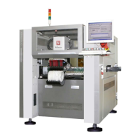
Appearance
<Figure 4-1> shows the appearance of Mx-Series SMD Mounter.
The appearances of Mx100/P, 200/P/TP and 400/P are basically the same.