4-24 Mx-Series Operation Manual
The placement position is obtained by compensating the position given by the Job program
with the offset obtained in Step 4.
6. If a defective component is found at Step 4, the head moves to the trash box and
discards it.
Vision System - Vision Processor Board
• Functions
The Vision Processor Board converts the vision information recognized
by the upward and downward cameras into component positioning
information and transmits it to the host
(VME) in order to properly pick and place the component.
The Vision Processor Board is the same for all models and supports up to
16 cameras.
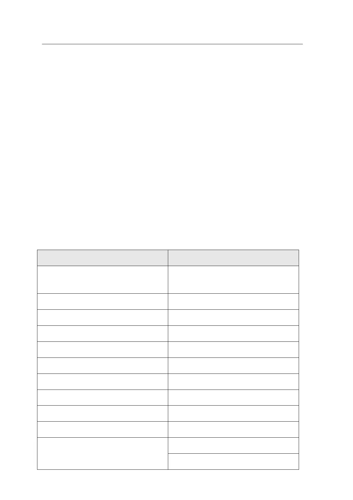
• Specification
<Table 4-5> summarizes the vision processor board specification
<Table 4-5 Mx-Series vision processor board specification>