MSDServoDrive AC-AC Operation Manual
moog
31
Id. no.:CA65642-001 Date:03/2012
[
Installation
]
to the glossaryto the table of contents
3.8 Control connections
Step Action Comment
Check whether a complete device setting is
already available, i.e. whether the drive has
already been projected
If this is the case, a special control terminal
assignment applies.
Please contact your project engineer to
obtain the terminal assignment.
Choose a terminal assignment.
Wire the control terminals with shielded
cables.
The following is strictly required:
ISDSH (X4/22) and ENPO (X4/10)
Ground the cable shields over a
wide area at both ends.
Cable cross-sections: 0.2 to
1.5mm²,incaseofferrules
with plastic sleeves maxi-
mum0.75mm²
Keep all contacts still open (inputs inactive)!
Check all connections once again!
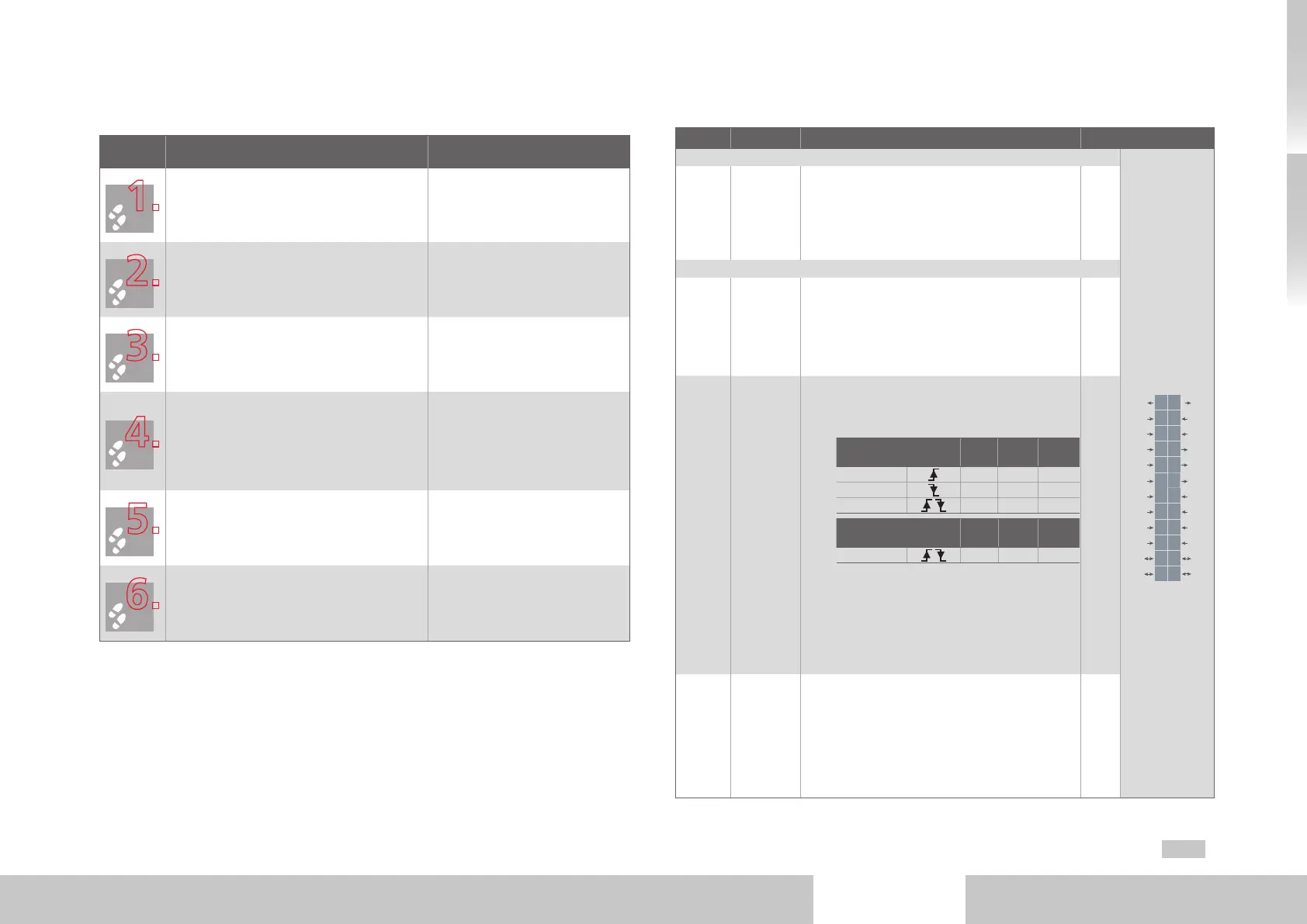
3.8.1 Specification of control connections
Des. Terminal Specification Electrical isolation
Analog inputs
REL
REL
ISDSH
ISD06
ISD05
ISD04
ISD03
ISD02
ISD01
ISD00
+24V
DGND
RSH
RSH
ENPO
OSD02
OSD01
OSD00
ISA1-
ISA1+
ISA0-
ISA0+
+24V
DGND
24
23
22
21
20
19
18
17
16
15
14
13
12
11
10
9
8
7
6
5
4
3
2
1
ISA0+
ISA0-
ISA1+
ISA1-
X4/3
X4/4
X4/5
X4/6
• U
IN
=±10VDC
• Resolution 12Bit; R
IN
approx.101kΩ
• Terminal sampling cycle in "IP mode" 125µs,
otherwise 1ms
• Tolerance: U±1% of the measuring range end
value
no
Digital inputs
ISD00
ISD01
ISD02
ISD03
ISD04
X4/15
X4/16
X4 /17
X4/18
X4/19
Standard input
• U
IN max
= +24VDC +20%
• I
max
at24V = 3mA typ.
• Switching level Low/High: ≤4.8V/≥18V
• Frequencyrange<500Hz
• Sampling cycle: 1ms
yes
ISD05
ISD06
X4/20
X4/21
Touch probe or standard input
• Input for touch probe for quick saving of pro-
cess data (e.g. actual position)
− Internal signal delay
Hardware version 0..1
Mini-
mum
Maxi-
mum
Typ.
ISD05
3µs 16µs 8µs
ISD05
4µs 27µs 15µs
ISD06
2µs
from Hardware version 2
Mini-
mum
Maxi-
mum
Typ.
ISD05 + ISD06
2µs
− Activation via ISD05/ISD06 = 15(PROBE)
• Standard input
− Frequency range ≤500Hz
− Sampling cycle: 1ms
• U
IN max
= +24VDC +20%
• I
IN max
at+24VDC =10mA, R
IN
=approx. 3kΩ
• Switching level Low/High: ≤4.8V/≥18V
yes
ENPO X4/10
• Deactivation of the restarting lock (STO) and
release of the power stage = High level
• OSSD-capable (from hardware version 2)
• Reaction time approx. 10ms
• Switching level Low/High: ≤4.8V / ≥18V
• U
IN max
= +24VDC +20%
• I
IN
at +24VDC = typ. 3mA
yes
Table 3.9 Specification of control connections X4

 Loading...

