MSDServoDrive AC-AC Operation Manual
moog
36
Id. no.:CA65642-001 Date:03/2012
to the glossaryto the table of contents
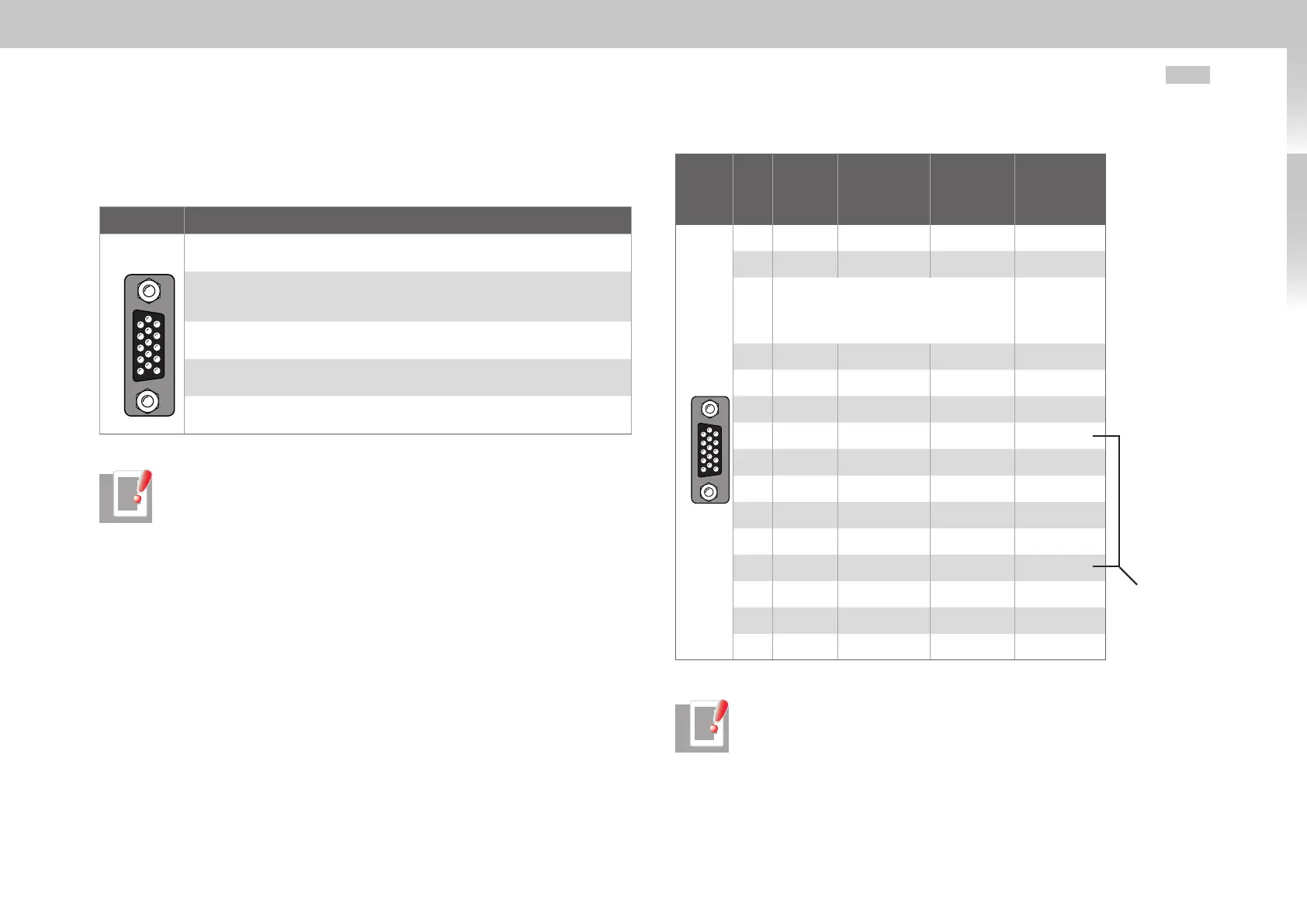
3.13.5 Connection for high resolution encoders
The interface X7 enables the evaluation of the following encoder types.
Fig. Function
54321
10 9 876
15 14 13 12 11
Encoder/ SSI
Sin/Cos encoder with index signal
e.g. Heidenhain ERN1381, ROD486
Heidenhain Sin/Cos encoder with EnDat interface
e.g. 13bit single-turn encoder (ECN1313.EnDat01) and 25bit multi-turn encoder
(EQN1325 -EnDat01)
Heidenhain encoder with digital EnDat interface
Single- or multi-turn encoder
Sin/Cos encoder SSI interface
e.g. 13bit single-turn and 25bit multi-turn encoder (ECN413-SSI, EQN425-SSI)
Sick-Stegmann Sin/Cos encoder with HIPERFACE® interface
Single- and multi-turn encoder, e.g. SRS50, SRM50
Table 3.16 Suitbale encoder types on X7
NOTES:
• The usage of encoders not included in the range supplied by Moog GmbH
requires special approval by Moog GmbH.
• The maximum signal input frequency is 500kHz.
• Encoders with a voltage supply of 5 V ± 5 % must have a separate encoder
cable connection. The encoder cable serves the detection of the actual
supply voltage on the encoder, whereby a compensation of the voltage drop
on the cable is achieved. Only the use of the encoder cable assures that the
encoder is supplied with the correct voltage. The encoder line must always
be connected.
Select the cable type specified by the motor or encoder manufacturer. Thereby please
observe the following boundary conditions:
• Always used shielded cables. The shielding must be placed on both sides of the
cable.
• Connect the differential track signals A, B, R or CLK, DATA to each other via
twisted wires.
• Do not separate the encoder cable, for example to route the signals via terminals in
the control cabinet.
Fig.
X7
Pin
Sin/Cos
and TTL
Sin/Cos
Absolute
value encoder
SSI/EnDat
Absolute
value en-
coder EnDat
(digital)
Absolute
value encoder
HIPERFACE®
54321
10 9 876
15 14 13 12 11
Encoder/ SSI
1 A- A- - REFCOS
2 A+ A+ - +COS
3
+5VDC ±5%, IOUT max=250mA
(150mA for Hardware versions 0..1),
monitoring via sensor line
7 to 12V
(typ. 11V)
maximum
100mA
The sum of the currents
drawn at X7/3 and
X6/4 must not exceed
the value given!
4 - Data + Data + Data +
5 - Data - Data - Data -
6 B- B- - REFSIN
7 - - - U
S
- Switch
8 GND GND GND GND
9 R- - - -
10 R+ - - -
11 B+ B+ - +SIN
12 Sense + Sense + Sense + U
S
- Switch
13 Sense - Sense - Sense - -
After connecting pin 7
and pin 12 a voltage of
11.8V will be applied to
X7, pin 3!
14 - CLK+ CLK+ -
15 - CLK - CLK - -
Table 3.17 Pin assignment of plug connection X7
NOTE: The encoder supply on X7/3 is short-circuit proof in both 5 V and
11V operation. The drive remains in operation such that on the evaluation of
encoder signals a corresponding error message can be generated.

 Loading...

