MSDServoDrive AC-AC Operation Manual
moog
41
Id. no.:CA65642-001 Date:03/2012
[
Installation
]
to the glossaryto the table of contents
3.15.3 Design with integrated braking resistor Size5 - Size 7
Servo drives of sizes 5-7 with liquid cooling can be equipped with an integrated braking
resistor as an option. You will find the related technical data in chapterA.2 from
page62.
3.15.4 Connection of an external braking resistor
DANGER CAUSED BY HIGH VOLTAGE! Danger to life! Terminal L+ (Size1 to
Size4) or BR+ (Size5 to Size7) is fixed connected to DC link (>300VDC). The
connection is not fuse protected inside the device. Never wire or disconnect
electrical connections while these are live! Always isolate the device from
the mains supply before working on it. Even 30 minutes after switching off
the mains supply dangerously high voltages of ≥50V may still be present
(capacitor charge). Therefore check for isolation from supply!
ATTENTION!
• Strictly follow the assembly instructions for the braking resistor.
• The temperature sensor (bimetal switch) on the braking resistor must be
wired in such a way, that the power stage is deactivated and the connected
servo drive is disconnected from the mains supply if the braking resistor
overheats.
• The externally installed braking resistor must not be less than the minimum
braking resistance permitted and the permitted continuous braking
power must not be exceeded, technical data see sectionA.2 starting with
page62.
• The braking resistor must be connected with a shielded cable.
!
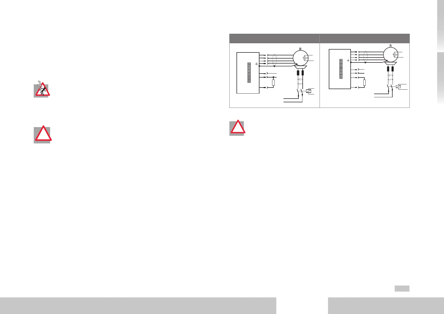
Size Size1 to Size4 Size Size5 to Size7
Motor
3
RB
L+
L-
Braking
resistor
U
V
W
DC teminal
~
X
12
Brake (+ )
Brake (-)
24 V DC
+
Motor
3
BR-
BR+
ZK-
ZK+
Braking
resistor
U
V
W
DC teminal
~
X
12
Brake (+ )
Brake (-)
24 V DC
+
Fig. 3.18 Connection of braking resistor
ATTENTION! No additional external braking resistor must be connected to the
servo drive with integrated braking resistor.
!

 Loading...

