MSDServoDrive AC-AC Operation Manual
moog
34
Id. no.:CA65642-001 Date:03/2012
to the glossaryto the table of contents
3.12 Option 2
Option 2 can be fitted with various technological options in the factory. As an example,
additional or special encoders can be evaluated.
All available options can be found in the MSDServoDriveOrdering Catalog. The user
manual for the respective option contains detailed information on commissioning.
3.13 Encoder connection
All encoder connections are located on the top of the unit.
Resolver
high-resolution encode
high-resolution encoder
Variant A
Variant B
Variant C
X (optional X )
78
X
6
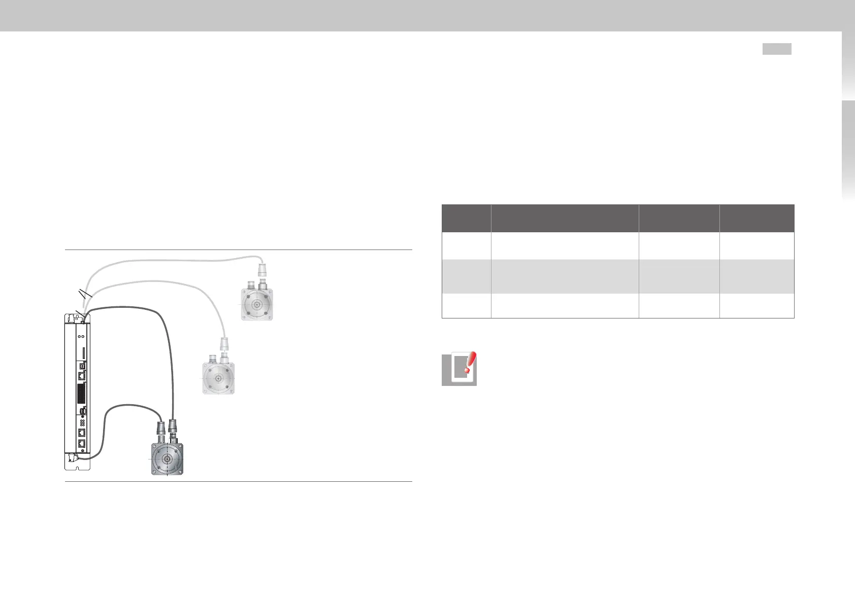
Fig. 3.15 Assignment motor/encoder cable
3.13.1 Encoder connection on servo motors
For connecting the servo motors please use the ready made-up motor and encoder
cables from Moog GmbH.
3.13.2 Assignment of motor/encoder cable to servo drive
Compare the type plates on the components. Make absolutely sure to use the correct
components according to a variant A, B or C!
Motor (with integrated encoder) Encoder cable
Connection of
servo drive
VariantA
with resolver
without further options
C08553-011-yyy X6
VariantB
Sin/Cos multi-turn encoder
with SSI/EnDat interface
CA58876-002-yyy X7
VariantC
Sin/Cos multi-turn encoder
with HIPERFACE
®
interface
CA58877-002-yyy X7
Table 3.13 Variants of motors, encoder type and encoder cable
NOTE: Do not split the encoder cable, for example to route the signals via
terminals in the control cabinet. The knurled screws on the D-Sub plug
housing are tightly locked!

 Loading...

