MSDServoDrive AC-AC Operation Manual
moog
66
Id. no.:CA65642-001 Date:03/2012
to the glossaryto the table of contents
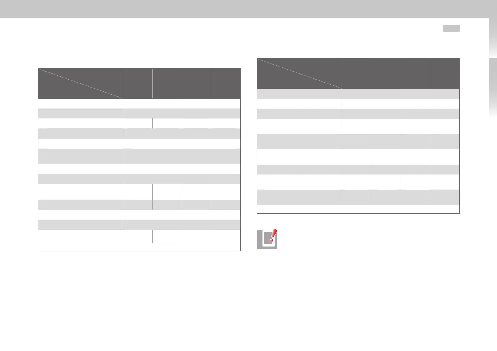
A.2.3 G392-090 to G392-170, air-cooled
Designation
Technical data
G392-090
G392-110
G392-143
G392-170
Output motor side
1)
Voltage 3-phase U
mains
Rated current effective (l
n
) 90A 110A 143A 170A
Peak current see TableA.3
Rotating field frequency 0 ... 400Hz
Output stage switching
frequency
4, 8, 12, 16kHz
Input mains supply side
Mains voltage (3x230V/ 3x400V/ 3x460V/ 3x480V) ±10%
Device connected load
1)
(with mains choke)
62kVA 76kVA 99kVA 118kVA
Current
1)
(with mains choke) 90A 110A 143A 170A
Asymmetry of the mains voltage ±3%maximum
Frequency 50/60Hz ±10%
Power loss at I
N
1)
1300W 1600W 2100W 2500W
1) Values related to a mains voltage of 3x400V
eff
and a switching frequency of 8kHz
Table A.9 Technical data G392-090 to G392-170, air-cooled
Designation
Technical data
G392-090
G392-110
G392-143
G392-170
DC link
Capacity 1060µF 2120µF 3180µF 4240µF
Brake chopper switch-on treshold
1)
820VDC
Minimum ohmic resistance of an exter-
nally installed braking resistor
3)
12 10 8.5 6.5
Brake chopper continuous power
with external braking resistor
1)
56kW 65kW 65kW 65kW
Peak brake chopper chopper with
external braking resistor
1)
56kW 67kW 79kW 103kW
Optional: internal braking resistor - - - -
Brake chopper continuous power
with internal braking resistor
- - - -
Peak brake chopper chopper with
internal braking resistor
- - - -
1) Values related to a mains voltage of 3x400V
eff
and a switching frequency of 8kHz
Table A.9 Technical data G392-090 to G392-170, air-cooled
NOTE: For further information on brake choppers please refer also to
chapter3.15.

 Loading...

