MSDServoDrive AC-AC Operation Manual
moog
18
Id. no.:CA65642-001 Date:03/2012
to the glossaryto the table of contents
Step Action Comment
Determine the pin assignment for your
device.
Section3.2 for Size1 to Size4
Section3.3 for Size5 to Size6A
Section3.4 for Size7
Connect all required input and output units
to the control terminals and, if necessary, to
the options.
Section3.8
Section3.11 and/or 3.12
Connect encoder, motor and, if necessary,
the external braking resistor.
Sections3.13, 3.14 and 3.15
Connect the PE-conductor and the supply
voltages.
Sections3.5 and 3.7
Continue with the commissioning in
chapter4.
Table 3.1 Electrical installation
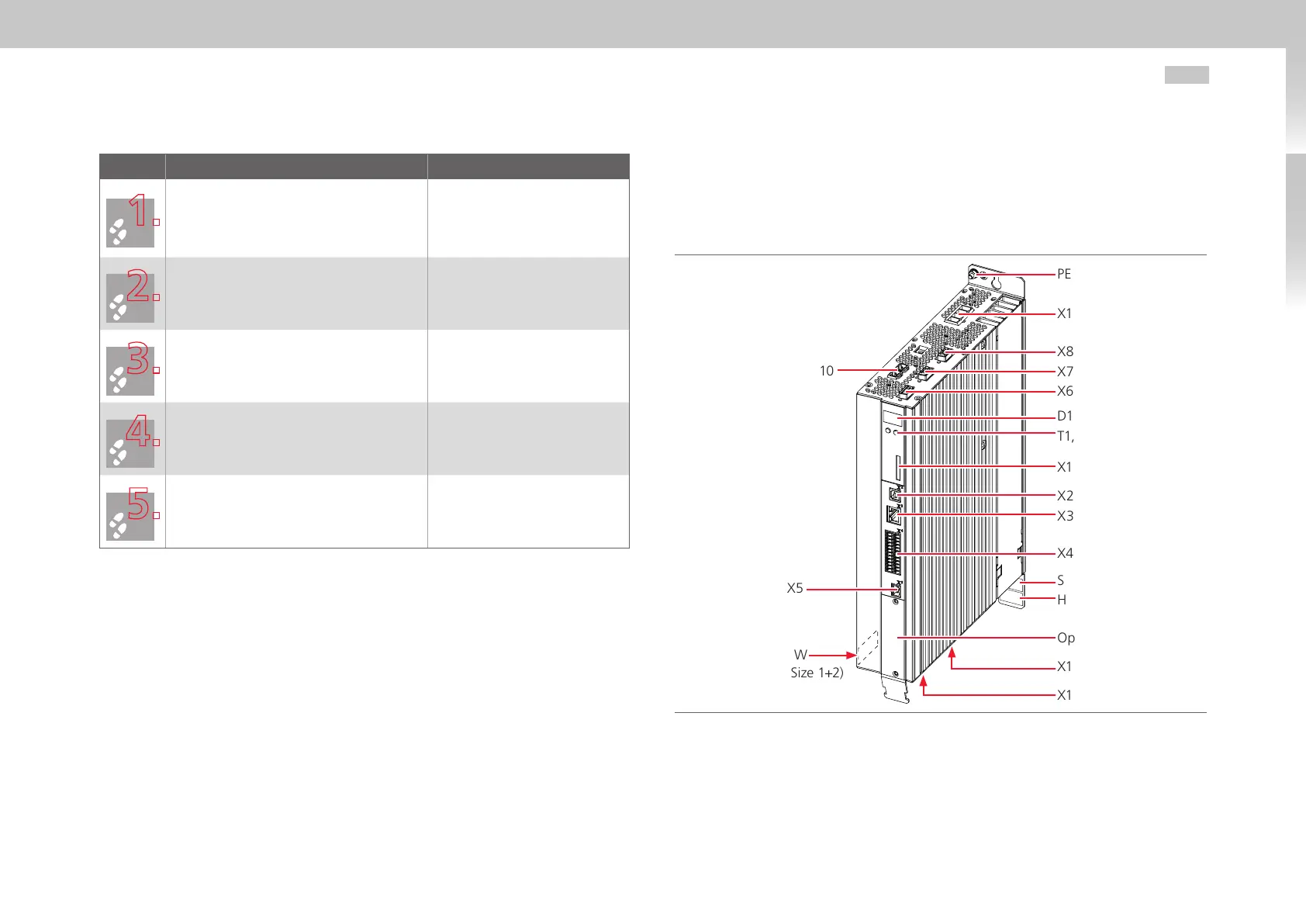
3.2 Overview of connections Size1 to Size4
The following shows the layout with the corresponding positions of plugs and terminals.
For better orientation we have identified the designations of plugs and terminals with an
abbreviation.
Fig. 3.1 Layout Size1 to Size4 (here: Size1)
PE
X11
X8
X7
X6
D1, D2
T1, T2
X1
X2
X3
X4
SW (Size3+4)
HW
Option1
X12
X13
X9, X10
X5
SW
(Size1+2)

 Loading...

