MSDServoDrive AC-AC Operation Manual
moog
19
Id. no.:CA65642-001 Date:03/2012
[
Installation
]
to the glossaryto the table of contents
USB 1.1
MMC slot
ISD00
ISD01
ISD02
OSD02
Relay
ENPO (STO)
Motor
3
Option 2
ISDSH (STO)
ISA00+
ISA00-
ISA01+
ISA01-
+24 V DC against
E/A-GND
+24 V (U
H
)
3
4
5
6
10
15
16
17
9
23
24
22
RSH
Diagnostic
STO
12
11
1
2,14
13
E/A-GND
Relay
Digital2
RB
L+
L-
U
V
W
6
8
ISD03
ISD04
ISD05
18
19
20
ISD0621
OSD01
8
Digital1
OSD00
7
Digital0
GND
OSD03
+
-
1
2
5
9
OSD04
54321
10 9876
15 14 13 12 11
DGND
DGND
43 21
9876
~
+
-
D1, D2
T1, T2
Ethernet
L1
K1
L2
L3
FN
L1
L2
L3
L1
PE
PE
K1
N
FN
L1
N
X11
X11
X10
X9
X1
X2
X3
X4
X8
X7
X6
X5
X13
X12
Front
Option 1
MMC
MultiMediaCard
INSERT
)
(+)
-
+
-
+
1
2
1
2
Network single-phase
Network triple-phase
24 V DC supply for
control electronics (U
V
)
Encoder
Resolver
e.g. add. encoder
Top
side
Analog set point 2
Analog set point 1
Service
interface
Service
interface
Control
Communication
Field buses
Bottom side
Braking
resistor
DC link
Brake (+
Brake (-)
Triggering of
motor brake
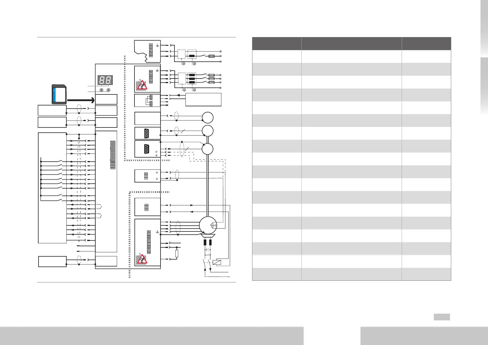
Fig. 3.2 Terminal diagram Size1 to Size4
Number Designation Details
D1, D2 7-segment display page46
T1, T2 Button page46
X1 Slot for M M C- ca rd page45
X2 USB1.1 interface page33
X3 Ethernet interface page33
X4 Control terminals page30
Option1 Communication page33
X11 Connection AC power supply page27
PE Connection PE conductor page24
X9, X10 Connection control supply page26
X8 (Option2) Technology page33
X7 Connection high resolution encoder page35
X6 Connection resolver page35
X5 Connection motor temperature monitoring page36
X13 Connection motor brake page32
X12
Connection motor, braking resistor
and DC link
page36
HW Hardware name plate page4
SW Software name plate -
Table 3.2 Legend to terminal diagram Size1 to Size4

 Loading...

