MSDServoDrive AC-AC Operation Manual
moog
30
Id. no.:CA65642-001 Date:03/2012
to the glossaryto the table of contents
3.7.3 Use with mains choke
The use of mains chokes is:
• necessary with all device from and including size Size5
• necessary when using servo drives in hostile industrial networks
• recommended to prolong the lifetime of DC link capacitors
3.7.4 Use with internal mains filter
Servo drives Size1 to Size5 are equipped with integrated mains filters. With the
measuring methods specified in the standard these servo drives comply with the EMC
safety-related requirements specified in IEC 61800-3 for ”Environment 1“ (residential
area C2) and “Environment 2“ (industrial area C3). More detailed information see
sectionA.6 „Mains filter“, page70.
ATTENTION! This is a restricted availability product in accordance with IEC
61800-3. In living areas this product may cause radio interference; in this case
the operator may be forced to apply appropriate measures.
3.7.5 Use with external mains filter
External radio interference suppression filters (CA71188-001 to CA71190-001,
CB09932-001) are available for the servo drives for Size6 and Size6A. With the
specified measuring method and the external mains filter these servo drives also ensure
compliance with the EMC product standard EN 61800-3 für “Environment 1” (residential
areas C2) and “Environment 2” (industrial area C3).
The question of whether size Size7 requires an external mains filter depends on the type
of connection and the local conditions. For this reason the use of a mains filter must
always considered individually and within the scope of a project.
In order to reach the use of longer motor cables and compliance with the EMC product
standard IEC 61800-3 for the “general availability” (residential area C1), additional
external mains filters are available for the devices with internal mains filters (Size1 to
Size5).
!
3.7.6 Terminal diagram precharge (only Size7)
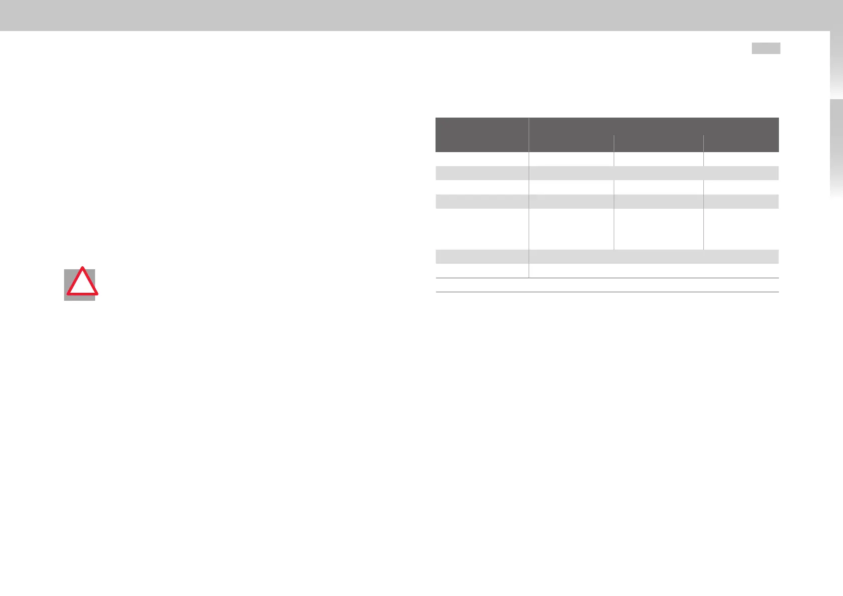
Designation
Specification
G395-250 G395-325 G395-450
Fuses1
250A 315A
400A
Fuses2, slow-blowing
6A
Mains filter (optional)
220A 300A
400A
Mains choke (U
k
=2%)
250A 325A
450A
K1
225A/ 110kW / 230V
(e.g. Siemens 3RT10
64-6AP36)
300A / 160kW / 230V
(e.g. Siemens 3RT10
66-6AP36)
400A / 200kW
/ 230V (e.g.
Siemens 3RT10
75-6AP36)
K2
12A / 5.5kW / 24V (e.g. Siemens 3RT10 17-1AB01)
K3
7A / 3kW / 24V (e.g. Siemens 3RT10 15-1AB01)
Recommended data for operation with asynchronous machine
Table 3.8 Specification of connection periphery
Wire the precharge circuitry as shown in Fig.3.14 as per standard with short-circuit
proof cables. The connected loads of the internal relay for terminals X44/3, 4 are
U
max
= 30VDC, I
max
= 6A. You should therefore use a contactor relay K3.
Control sequence
• Precharge of DC link
Switch S1 “Mains supply On” is switched on. The precharging contactor K2 closes and
the DC link is precharged via internal precharging resistor on terminal X45. The main
contactor K1 remains open for the time being.
• Precharging completed
At a defined DC link voltage the contact of the internal relay on terminal X44/3.4
is closed. The contactor relay K3 closes and connects the main contactor K1. The
precharging contactor K2 is opened via an auxiliary contact (normally closed contact)
on K1. The MSDServoDriveAC-AC changes to standby.
• Switching off
The switch S1 “Mains supply Off” completely disconnects the servo drive from the
mains supply.

 Loading...

