MSDServoDrive AC-AC Operation Manual
moog
32
Id. no.:CA65642-001 Date:03/2012
to the glossaryto the table of contents
Des. Terminal Specification Electrical isolation
Digital outputs
REL
REL
ISDSH
ISD06
ISD05
ISD04
ISD03
ISD02
ISD01
ISD00
+24V
DGND
RSH
RSH
ENPO
OSD02
OSD01
OSD00
ISA1-
ISA1+
ISA0-
ISA0+
+24V
DGND
24
23
22
21
20
19
18
17
16
15
14
13
12
11
10
9
8
7
6
5
4
3
2
1
OSD00
OSD01
OSD02
X4/7
X4/8
X4/9
• no destruction in short-circuit incidents (+24V
-> GND), however, device may switch off for a
short time.
• I
max
=50mA, PLC-compatible
• Terminal sampling cycle =1ms
• High-side driver
yes
STO ("Safe Torque Off")
ISDSH
(STO)
X4/22
• Request input "STO" = Low level
• OSSD-capable (from hardware version 2)
• Switching level Low/High: ≤4.8V / ≥18V
• U
IN max
= +24VDC +20%
• I
IN
at +24VDC = typ. 3mA
yes
RSH
RSH
X4 /11
X4/12
Diagnosis STO, both tripping chan-
nels active, one normally open
with self-resetting circuit breaker
(polyswitch)
• 25V/200mAAC, cosϕ=1
• 30V/200mADC, cosϕ=1
X4/12
X4/11
yes
Relay output
REL
X4/23
X4/24
Relay, 1 normally open
• 25V/1.0AAC, cosϕ=1
• 30V/1.0ADC, cosϕ=1
• Switching delay approx.10ms
• Cycle time 1ms
X4/23
X4/24
Auxiliary voltage
+24 V
X4/2
X4/14
• Auxiliary voltage to feed the digital inputs
• U
H
=U
V
-∆U (∆U typically approx. 1.2V), no
destruction in short-circuit incidents
(+24V -> GND), however, device may switch
off for a short time.
• I
max
=80mA (per pin) with self-resetting circuit
breaker (polyswitch)
yes
Digital ground
DGND
X4/1
X4/13
Reference ground for 24V, I
max
=80mA (per pin),
Hardware versions 0..1 with self-resetting circuit
breaker (polyswitch)
yes
Table 3.9 Specification of control connections X4
NOTE: High-resistance isolation to device ground
With too high currents flowing through the ground terminals a high
resistance isolation from the device ground is possible. This can lead to
malfunction of the drive. To prevent this, you must avoid circulating currents
in the wiring.
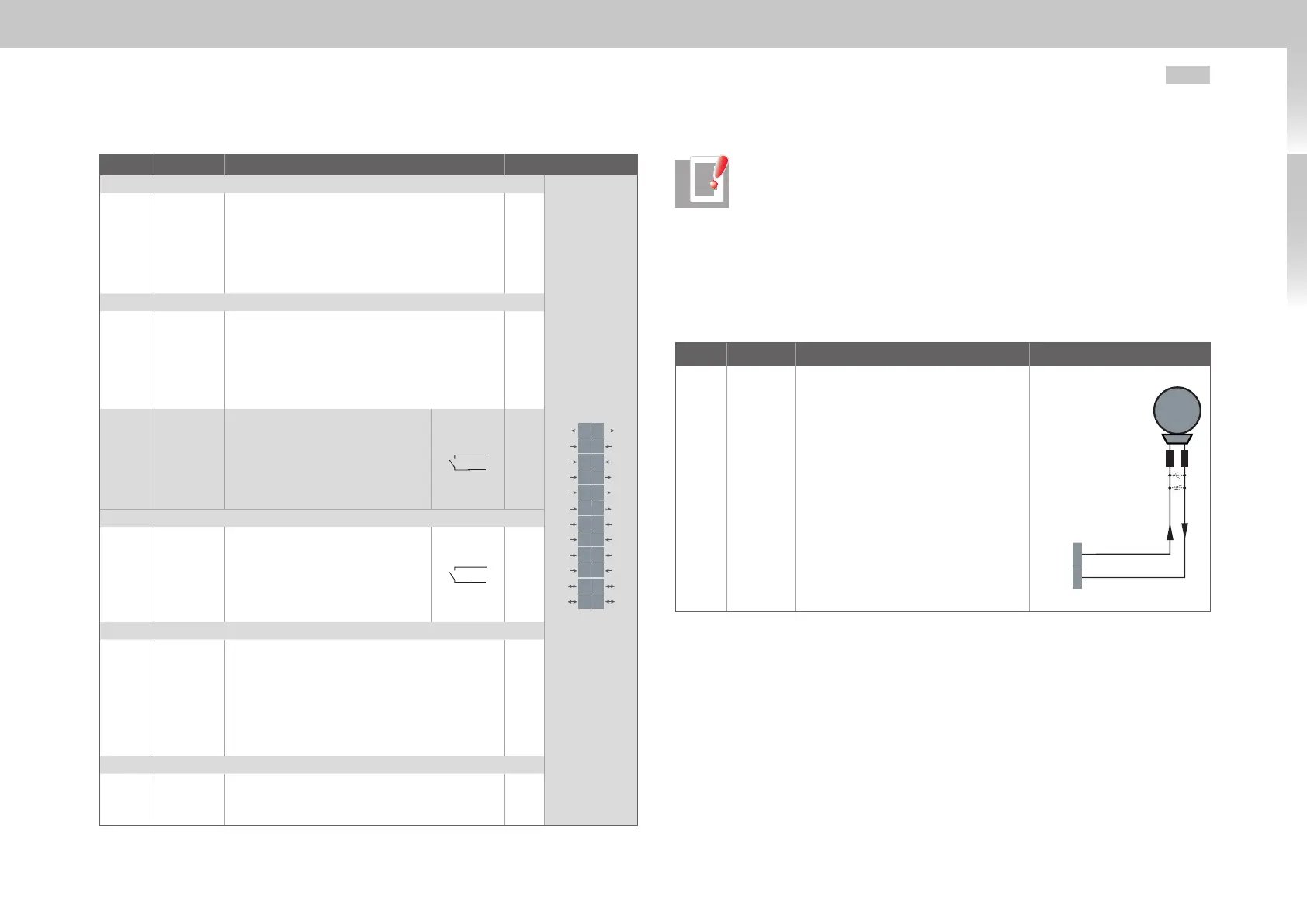
3.8.2 Brake driver
On Size1 to Size4 plug X13 serves the purpose of connecting a motor brake.
Des. Terminal Specification Connection
OSD03
GND
X13/1
X13/2
• Short-circuit proof
• Voltage supply through control sup-
ply U
V
to X9/X10.
• U
BR
=U
V
-∆U`
(∆U` typically approx.1.4V)
• To trigger a motor brake of up to
I
BR
=2.0Amaximum, for brakes with
higher current requirements a relay
must be connected in series.
• Overcurrent causes shut down
• Can also be used as configurable
digital output.
• Interruptible cable breakage monitor-
ing<500mAtypicallyincondition
"1" (up to relay)
X13
M
Brake (+)
OSD03 1
GND 2
Table 3.10 Specification of terminal connections X13 (Size1 to Size4)

 Loading...

