MSDServoDrive AC-AC Operation Manual
moog
53
Id. no.:CA65642-001 Date:03/2012
[
Diagnosis
]
to the glossaryto the table of contents
5 Diagnosis
5.1 Status display on device
The 7-segment display on the device shows the device states.
5.1.1 Device states
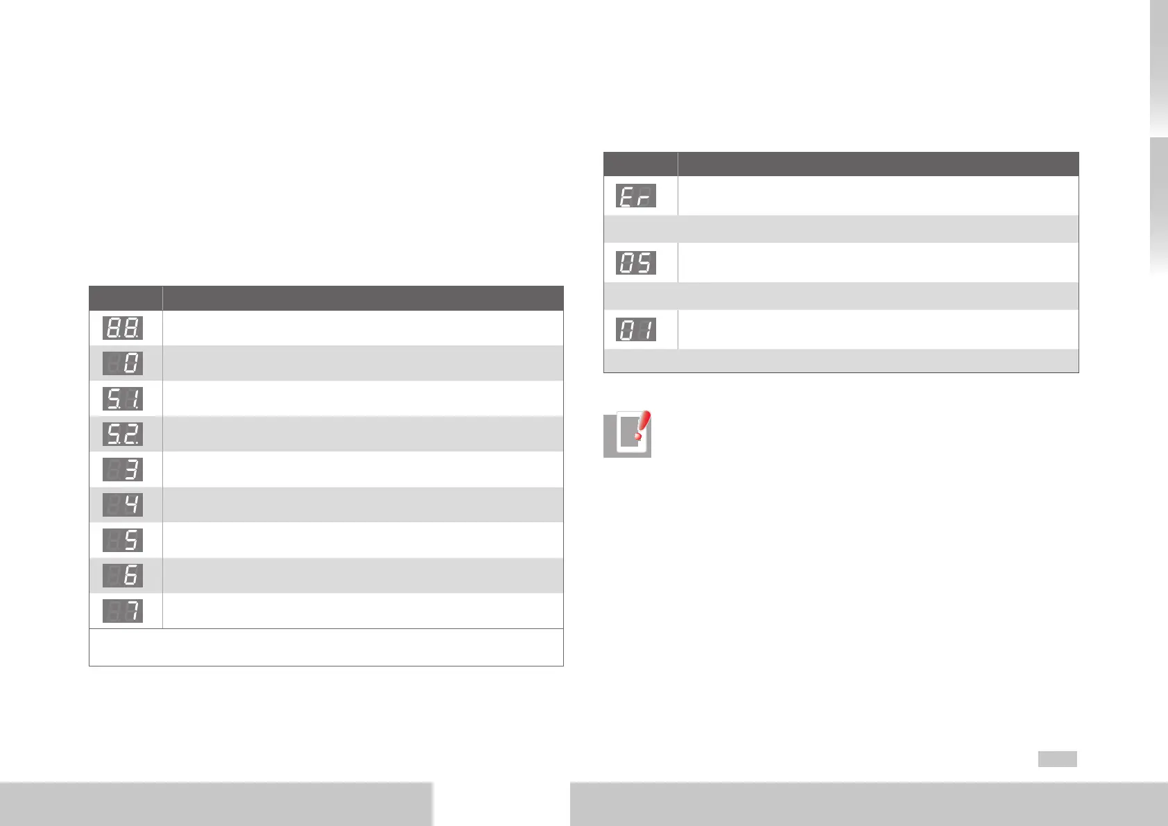
Display System status
Device in reset state
Automatic initializing during start-up of device
*)
Not ready to switch on (no DC link voltage)
1)
*)
Starting lockout (DC link OK, power stage not ready)
1)
Switched on (drive powered)
Switched on (drive energized)
2)
Drive ready (drive energized and ready for setpoint specification)
2)
Quick stop
2)
Fault reaction active
2)
*) it is not a „safe indication“ as specified in EN EN61800-5-2.
1) S. flashes when the function STO (Safe Torque Off) is active, display goes out when the function is inactive.
2) This point flashes when the power stage is active.
Table 5.1 Device states
5.1.2 Error display
In each individual case the error codes will be displayed by the 7-segment display. Each
error code consists of the repeating sequence of ►“Er“ ►Error number ►Error location.
Display Meaning
Device error
↓ Display changes after approx. 1s
Error number (decimal)
Example: 05 = Overcurrent
↓ Display changes after approx 1s
Error location (decimal)
Example: 01 = Hardware monitoring
↑ After approx. 1s the display jumps back to ER
Table 5.2 Representation of the error code
NOTES:
• Acknowledge error
The errors can be acknowledged in accordance with their programmed
reaction (ER) or only reset via a 24 V reset (X9/10) (ER.). Errors marked with
a dot can only be reset, after the cause of the error has been eliminated.
• Error code
Detailed information concerning the error codes and error management
can be found in the “MSDServoDriveApplication Manual”.

 Loading...

