MSDServoDrive AC-AC Operation Manual
moog
26
Id. no.:CA65642-001 Date:03/2012
to the glossaryto the table of contents
3.7 Connection of supply voltages
The power supply for the MSDServoDriveAC-AC is separated into the supplies for
control and power sections. In the connecting sequence the control supply must always
be connected first, so that triggering of the MSDServoDriveAC-AC can first be
checked or the device can be parameterized for the intended application.
DANGER CAUSED BY HIGH VOLTAGE: Dangerous voltage may be applied
to the device, even if the device does not emit any visual or audible signals/
indications (e.g. with mains voltage applied to terminal X11 and missing
control supply (+24 V DC on X9/X10 or X44)!
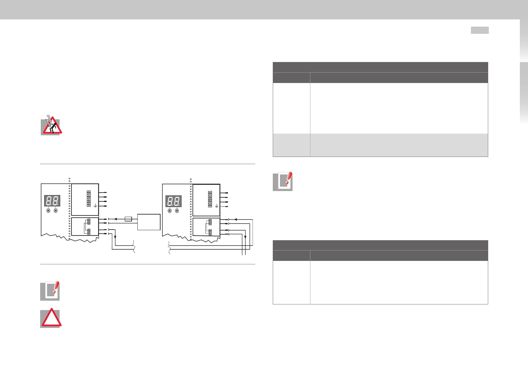
3.7.1 Connection control supply (24VDC)
L1
L2
L3
Network triple-phase
+24 V DC ±20%
ext. voltage
source
D1 D2
next servo controller
max. 10 A gG
Loop-through only pos-
sible with Size 1 to Size 4
1
2
1
2
L1
L2
L3
D1 D2
1
2
1
2
+
-
+
-
+
-
+
-
Top side Top side
Device 1
X11
X9
X10
X11
X9
X10
Device 2
Network triple-phase
Fig. 3.11 Connection control supply Size1 to Size6A
NOTE: The connection of control supply for Size7 can be found in Fig. 3.14
on page 29.
ATTENTION! Generally apply suitable measures to provide adequate line
protection.
!
Control supply Size1 to Size6A
Terminal/Pin Specification
X9/1 = +
X9/2 = -
• U
V
=24VDC ±20% (Size5 to Size6A +20/-10%), stabilized and filtered
• maximum starting and continuous currents see tableA.15 on page68.
• Current carrying capacity of terminal continuously maximum 10 A (Size5 to
Size6A maximum 8 A), internal polarity reversal protection
• The power supply unit used must have a safe and reliable isolation towards
the mains network, as per EN 50178 or EN 61800-5-1.
• Internally interconnected with X10
X10/1 = +
X10/2 = -
• Current carrying capacity of terminal continuously maximum 10 A (Size5 to
Size6A maximum 8 A)
• Internally interconnected with X9
Table 3.5 Specification control supply Size1 to Size6A
NOTE: With sizes Size1 to Size4 the external voltage source not only supplies
the control unit, but also the output for the motor holding brake. If this
output is active, the current for the control unit plus the current for the motor
holding brake and additional current requirements for digital inputs and
outputs flows through terminal X9. Please take this into consideration when
rating the voltage source for the control unit and when looping through to
other equipment. The current demand for the individual devices can be found
in the appendix on page68 in tableA.15.
Control supply Size7
Terminal/Pin Specification
X44/1 = +
X44/2 = -
• U
V
=24VDC ±10%, stabilized and filtered
• maximum starting and continuous currents see tableA.15 on page68
• Current carrying capacity of terminal continuously maximum 10 A, internal
polarity reversal protection
• The power supply unit used must have a safe and reliable isolation towards
the mains network, as per EN 50178 or EN 61800-5-1.
Table 3.6 Specification control supply Size7

 Loading...

