MSDServoDrive AC-AC Operation Manual
moog
29
Id. no.:CA65642-001 Date:03/2012
[
Installation
]
to the glossaryto the table of contents
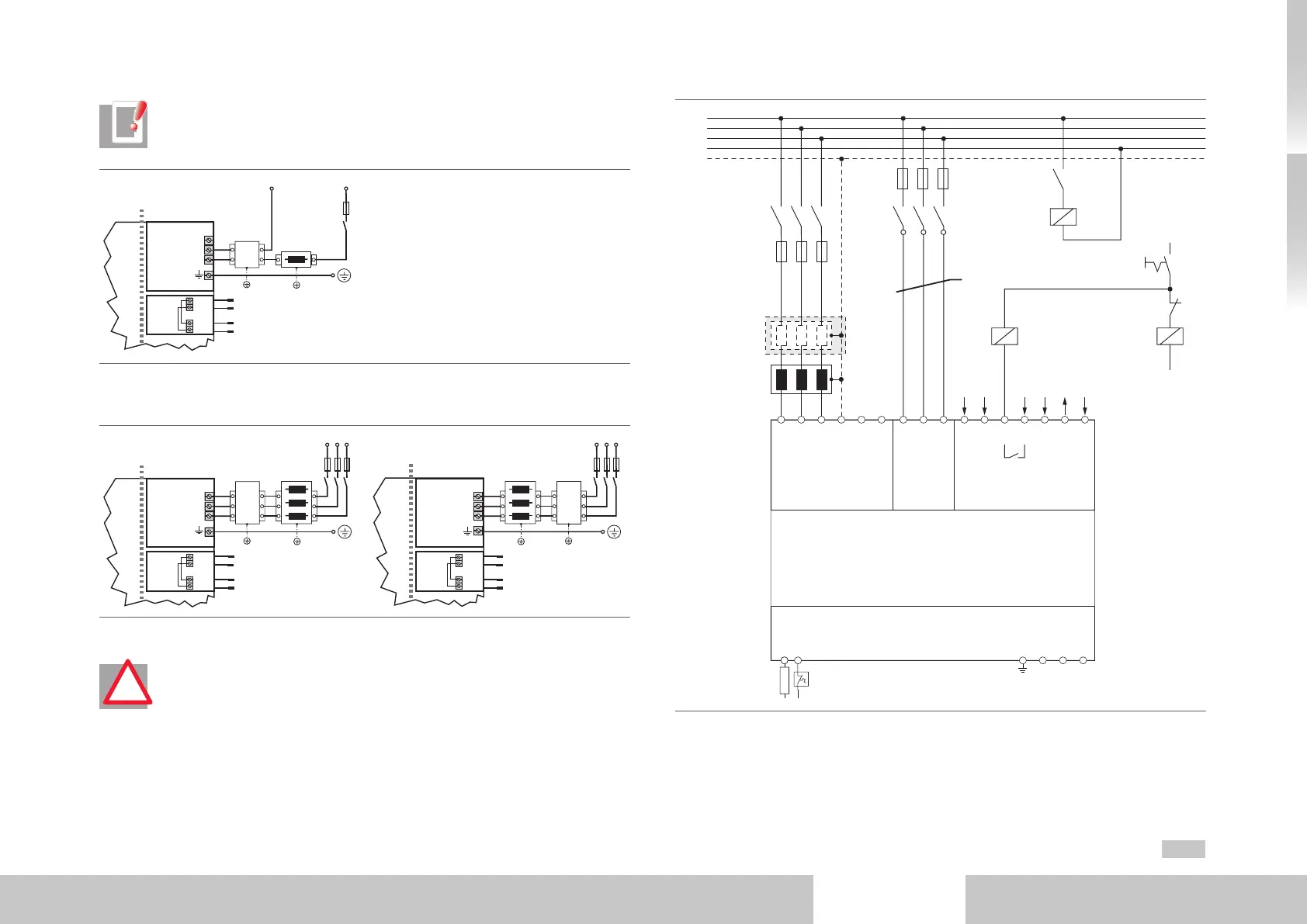
NOTE: Before commissioning the value of the connected mains voltage must
be set in the servo drive (factory setting =3x400VAC).
L1
N
1
2
1
2
+
-
+
-
Top side
Size 1
L1
K1
N
FN
Filter
Choke
X11
X10
X9
Network single-phase
Fig. 3.12 Connection of mains supply 1x230V
L1
L2
L3
1
2
1
2
+
-
+
-
+
-
+
-
Top side Top side
L1
L2
Size 1 to Size 4 Size 5 to Size 6a
L3
L1
K1
L2
L3
FN
Network triple-phase
1
2
1
2
Filter Choke
L1
K1
L2
L3
FN
FilterChoke
X11
X10
X9
X11
X10
X9
Network triple-phase
Fig. 3.13 Connection of mains supply 3x230/400/460/480V for Size1 to Size6A
ATTENTION! For devices of sizes Size5 to Size7 a mains choke is mandatory.
Due to the different precharging technology in these devices you must make
sure that the mains choke is installed between servo drive and mains filter
(see Fig. 3.13 and Fig. 3.14).
!
L1
L2
L3
short-circuit proof
Mains Precharge Control
supply
Supply and
triggering of
motor brake
K2K1Main contactor
N
PE
K2
K1
K3
24 V
24 V
S1
GND
GND
GND
24 V
OSD03
GND
G395-250
G395-325
G395-450
internal
relay
RB
+
L1 L2
L3 PE
WVUPE
ZK- ZK+
X11
L1 L2
L3
X45
X12
1 2
3 4 5 6 7
X44
K1
K3
Fuses 1
Fuses 2
Mains filter
(optional)
Mains choke
Braking resistor
Precharging connection
Fig. 3.14 Connection of precharge, control and mains supply 3x230/400/460/480V for Size7

 Loading...

